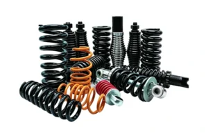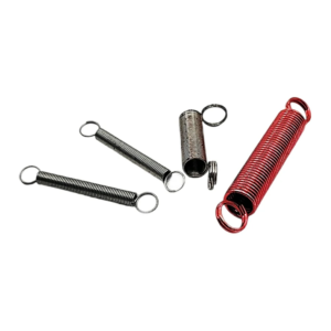
Choosing the right spring starts with the job it must perform. A spring that fits the available space may still deliver the wrong force, buckle under compression, or fail after a few thousand cycles. The right design must match the required motion, load, travel, installation space, operating environment, and service life.

Start by identifying the motion: compression, extension, rotation, or constant-force movement. Then define the working load and travel, check the available space, and select a material that can withstand the temperature, corrosion exposure, and fatigue demands. Finally, confirm that the design can be manufactured consistently and decide whether a stock spring or a custom design makes more sense.
This guide follows that sequence. It explains which spring types suit different mechanisms, which dimensions and performance values belong on a drawing, and which design details determine whether a spring can be wound, formed, heat-treated, and installed reliably. By the end, you should be able to produce a spring specification that is complete enough to be evaluated, tested, and manufactured—not simply a part that looks right on paper.
→
Spring Type
→
Parameters
→
Material
→
DFM Review
→
Stock or Custom
1. Start with the Application, Not the Spring
Choose a spring based on the motion and force required by the mechanism. Starting with a familiar spring type can lead to unnecessary compromises in packaging, performance, or service life.
1.1 What Motion Does Your System Need? Push, Pull, Twist, or Store Energy?
Identify what the spring must do during normal operation.
- Resist compression: Choose a compression spring when a component pushes against it and the spring returns the component when the load decreases. Examples include engine valve springs, push buttons, and suspension mechanisms.
- Resist extension: Choose an extension spring when the mechanism pulls the spring longer and needs a restoring force. Examples include door mechanisms, trampolines, and return linkages.
- Resist rotation: Choose a torsion spring when a rotating component needs a restoring torque. Examples include hinges, clips, and mechanical latches. (See our comparison: Spiral Spring vs. Torsion Spring.)
- Provide a specific force or compact axial resistance: Consider a constant-force spring for long, nearly uniform pulling force, a wave spring for axial preload in limited space, or a disc (Belleville) spring for high axial loads over short deflections.
These categories are not interchangeable. A compression spring cannot automatically replace a torsion spring simply because both fit inside the same housing. The load direction, mounting arrangement, and force-displacement behavior must match the mechanism.
1.2 Load, Travel, and Space: The Three Constraints That Drive Everything
Load, travel, and available space must be evaluated together. Changing one can force changes to the other two.
- Load: How much force must the spring produce or resist?
- Travel: How far will the spring move between its unloaded and working positions?
- Space: What are the maximum and minimum permitted dimensions in the assembly?
For a compression spring, a required load at a known deflection helps determine the spring rate. The available outside diameter, inside diameter, and working height then limit the possible wire diameter and coil geometry.
Three constraints to check together
↔
Required Travel
↔
Available Space
Changing any one of these can affect spring rate, dimensions, stress, stability, and cost.
For example, if a spring must produce a high force within a short working height, simply increasing the number of coils may not work. More active coils generally reduce the spring rate, while a thicker wire generally increases it. The final geometry must also leave enough room before the spring reaches solid height.
1.3 Duty Cycle and Life Expectancy
A spring that operates once a day faces different demands from one that cycles several times per second. Define the expected operating life before selecting the material and stress level.
- Static or occasional loading: The spring may remain compressed or operate infrequently. Permanent deformation and stress relaxation may matter more than high-cycle fatigue.
- Regular cycling: Repeated loading makes operating stress, surface condition, and material quality increasingly important.
- High-frequency cycling: Springs in engines, pumps, and vibrating equipment need careful fatigue evaluation and attention to resonance where relevant.
- Long service life: If the design requires hundreds of thousands or millions of cycles, state the target cycle count and test conditions in the specification.
Do not specify only that a spring must be “durable.” State the required cycle count, load range, operating frequency, and environment. These details give the manufacturer a basis for evaluating fatigue risk.
2. Spring Type Comparison: A Selection Table, Not an Encyclopedia
Use this table to narrow the options. The final choice still depends on the required force, dimensions, mounting method, and operating conditions. For a direct deep-dive on the most common confusion, read Compression vs. Extension Springs.
| Spring Type | Loading | Typical Application | Installation Characteristics | Common Failure Risks | Stock or Custom |
|---|---|---|---|---|---|
| Compression spring | Axial compression | Valves, shock absorption, push buttons | May need a guide to prevent buckling | Fatigue, permanent set, buckling | Both |
| Extension spring | Axial tension | Trampolines, door locks, return mechanisms | Requires suitable hooks, loops, or end attachments | Hook fracture, fatigue, loss of initial tension | Both |
| Torsion spring | Rotational torque | Hinges, clips, latches | Leg geometry and support points control installation | Leg fatigue, stress concentration, incorrect rotation | Mostly custom |
| Wave spring | Axial compression | Preload in compact assemblies | Useful where axial space is limited | Fatigue, uneven loading, friction between layers | Mostly custom or application-specific stock |
| Belleville spring | High axial load, relatively small deflection | Bolt preload, load control, overload protection | May be stacked in series or parallel | Edge yielding, fatigue, incorrect stacking | Many standard options |
| Constant-force spring | Extension with nearly constant force over its working range | Counterbalances, sliding covers, retracting mechanisms | Uses a coiled strip and suitable mounting geometry | Strip fatigue, edge damage, incorrect winding | Mostly custom or application-specific stock |
2.1 When a Compression Spring Is the Default Choice
A compression spring is a practical starting point when the mechanism needs axial force and has enough space for the spring to shorten under load.
It often suits designs where a plunger, valve, or moving component compresses the spring along its axis. Stock and custom compression springs can be suitable when their free length, working load, spring rate, diameters, and solid height match the assembly. (If you are new to the terminology, read What is a Compression Spring?)
Check stability before settling on the design. A long, slender compression spring can bow sideways under load, especially without suitable guidance. If the spring operates inside a housing or over a shaft, include those dimensions in the initial design rather than treating them as installation details to resolve later.
2.2 When You Should Consider Wave, Belleville, or Constant Force Instead
Consider an alternative when a conventional helical compression spring cannot meet the packaging or force requirements efficiently.
- Choose a wave spring when axial space is limited and the assembly needs preload or controlled deflection. Confirm the available working travel and load range; a compact profile does not guarantee that every load requirement can be met.
- Choose a Belleville spring when the application needs high axial force over a relatively short displacement, such as maintaining preload in a bolted joint. The load-deflection curve changes with geometry and stacking arrangement.
- Choose a constant-force spring when a mechanism needs a nearly uniform pulling force over a defined extension range. Check the available strip travel, mounting arrangement, and fatigue requirements.
Do not select these types solely because they look more compact. Compare their force-displacement behavior and installation requirements with the actual operating conditions.
3. Define the Parameters That Actually Matter
A useful spring specification defines the required performance and the physical limits. The manufacturer can often calculate the detailed geometry, but only if the working conditions are clear.
3.1 Load and Spring Rate: What You Need to Specify vs. What We Can Calculate
For a linear compression spring operating within its intended range, the relationship between load and deflection can be approximated by:
Spring rate
k = F / δ
Where:
k= spring rateF= applied loadδ= deflection from the reference position
Approximate rate for a close-coiled helical compression spring:
k = Gd⁴ / (8D³N)
Where G is the material’s shear modulus, d is wire diameter, D is mean coil diameter, and N is the number of active coils.
The formula is a starting point for a conventional helical spring, not a complete design verification. End conditions, material behavior, stress corrections, and manufacturing details can affect the final result. For a deeper walkthrough on how formulas relate to failure modes and sourcing, see our Flat Spring Guide.
Specify these values when they are known:
- Required load at one or more working heights.
- Required travel or deflection.
- Installed height or working height.
- Any initial preload or minimum force requirement.
The manufacturer can usually calculate or recommend:
- Wire diameter and mean coil diameter.
- Active coil count and free length.
- Spring rate and estimated solid height.
- Suitable material, end form, and manufacturing process.
For an extension spring, also state whether initial tension is required. Initial tension is the force needed to begin separating the coils and can materially affect the force delivered at small extensions.
3.2 Deflection and Travel: Working Height vs. Free Length
Free length is not the same as working height. Free length describes the spring’s unloaded length. Working height is its length at a specified operating load.
For a compression spring, axial deflection is the difference between free length and the loaded length, assuming the specified reference condition:
Deflection = Free Length − Working Height
Solid height is the approximate length of a compression spring when its coils are fully compressed into contact. The available working height must remain compatible with solid height and the required operating travel. The exact relationship depends on end configuration and spring geometry.
Ignoring solid height can cause a spring to reach coil bind before the mechanism completes its stroke. At that point, the spring can no longer provide the intended travel, and the load may rise sharply. This can damage the spring or surrounding components.
When specifying a compression spring, provide the free length, the required working height or deflection, and the load at that position. If the spring must never reach solid height during normal operation, state that requirement explicitly.
3.3 Diameter Constraints: OD, ID, and Guide Clearance
Specify the diameter that controls the fit in your assembly. For a compression spring, the key dimensions are:
- Outside diameter (OD): The maximum external diameter of the spring.
- Inside diameter (ID): The open diameter inside the coils.
- Mean coil diameter (D): The average diameter of the coil, commonly calculated as the outside diameter minus one wire diameter.
A spring fitted over a shaft needs enough inside-diameter clearance to move without binding. A spring installed inside a tube needs enough clearance between its outside diameter and the tube’s inside diameter. Too little clearance can cause friction or jamming; too much clearance may reduce guidance and allow the spring to bow.
For small and medium guided springs, a diametral clearance of roughly 0.5–1.0 mm can serve as an initial design estimate in some applications. It is not a universal standard. Longer springs, larger diameters, tight tolerances, coatings, temperature changes, and side loads can require different clearances.
Confirm the fit using the actual shaft or housing dimensions and their tolerances. If the spring operates at elevated temperatures or receives a surface coating, include those effects in the clearance calculation.
3.4 End Types and Attachment Methods
End geometry affects how the spring seats, transfers load, and fits into the assembly.
- Compression springs: Open ends are simple to manufacture. Closed ends provide more consistent seating, while closed-and-ground ends can improve contact on flat surfaces. Grinding adds a manufacturing operation and may affect cost.
- Extension springs: Hooks, loops, and other end attachments determine how the spring connects to the mechanism. Their shape and bend radius affect both installation and fatigue strength. (See our guide on evaluating extension spring manufacturers.)
- Torsion springs: Leg angle, leg length, and contact points determine how torque transfers into the assembly. Incorrect leg geometry can prevent proper installation or cause unwanted side loading. (See 10 Specifications to Confirm Before Ordering Custom Torsion Springs.)
Show the required end form on the drawing or provide a clear reference part. For extension and torsion springs, include attachment geometry and operating orientation. A generic note such as “standard hook” may not define the shape or fit needed for the application.
3.5 Tolerances: What Standard vs. Precision Really Means
Specify tight tolerances only on dimensions that affect fit, force, or function. A tolerance that does not improve performance can increase inspection time, production cost, and rejection risk.
Commercial spring tolerances vary with spring type, wire diameter, free length, geometry, material, and manufacturing process. The table below gives illustrative starting ranges, not universal limits. Always confirm achievable tolerances with the manufacturer before releasing a drawing.
| Parameter | Standard / Commercial (illustrative) | Precision (illustrative) | What It Affects |
|---|---|---|---|
| Free length | ±1% to ±2% of free length, or ±0.25–0.5 mm for small springs | Tighter than ±1%, subject to process capability | Installed height, preload, solid-height margin |
| Outside diameter (OD) | ±0.2–0.5 mm typical for small/medium springs | ±0.05–0.15 mm where process allows | Housing clearance, guide fit |
| Inside diameter (ID) | Derived from OD and wire tolerance | Can be controlled more tightly with grinding or sizing | Shaft clearance, binding risk |
| Wire diameter | Per wire standard tolerance | Selected wire lots or post-processing | Spring rate, stress, fit |
| Load at working height | ±10% to ±15% typical | ±5% or tighter with 100% load testing | Force delivered at installed position |
| Spring rate | ±10% typical | ±5% or tighter with process control | Force change over travel |
| Solid height | Depends on end grinding and wire tolerance | Controlled by grinding and coil count | Coil-bind margin, travel limit |
| Perpendicularity / squareness | Standard commercial | Improved by closed-and-ground ends | Seating, side load, buckling |
Before setting a tolerance, ask three questions:
- What assembly problem occurs if the dimension varies?
- Does the spring need to meet a dimensional tolerance, a load tolerance, or both?
- Can the selected process maintain that tolerance at the required production volume?
For a spring that controls a valve or maintains contact pressure, load at a defined working height may be more important than free length alone. State the test height, acceptable force range, and measurement conditions so the supplier can verify the performance you need.
4. Material and Environment: Where Most Spring Failures Start
Select material based on operating temperature, corrosion exposure, cyclic loading, magnetic requirements, and cost. A material that performs well in a dry room may not survive in a hot, chloride-rich, or continuously vibrating environment. For more details, visit our materials selection page.
4.1 Temperature: From Standard Carbon Steel to Inconel
Temperature affects spring strength, stress relaxation, fatigue behavior, and corrosion resistance. The alloy name alone does not establish a safe operating limit. Grade, heat treatment, stress level, exposure time, and environment all matter.
| Material | Typical Strength | Typical Temperature Range (reference only) | Temperature Considerations | Common Applications |
|---|---|---|---|---|
| High-carbon spring steel / music wire | High strength and good spring performance at suitable conditions | Approx. room temperature to ~120–150 °C, depending on grade and stress | Elevated temperatures can increase stress relaxation | General-purpose springs, mechanisms, and precision components |
| 302 or 304 stainless steel | Useful combination of spring performance and corrosion resistance | Approx. up to ~250–300 °C for many spring applications, subject to stress and grade | Allowable stress and life depend on the actual grade and conditions | Food equipment, consumer products, and general corrosion-resistant mechanisms |
| 316 stainless steel | Improved resistance to many chloride-containing environments compared with 304 | Similar order to 304; not automatically a high-temperature upgrade | Mechanical properties and stress limits must be checked | Marine-related equipment and applications exposed to corrosive environments |
| 17-7 PH stainless steel | High strength after suitable heat treatment | Approx. up to ~300–350 °C depending on condition and load | Can retain useful mechanical properties at elevated temperatures | Precision springs requiring strength and corrosion resistance |
| Inconel X-750 or other suitable nickel alloys | Designed for demanding high-temperature or corrosive conditions | Some grades used at several hundred °C; verify exact alloy and stress | Permissible limit must be verified for the exact alloy and stress level | High-temperature machinery, aerospace-related equipment, and demanding industrial systems |
Do not select a high-temperature alloy using temperature alone. Provide the operating temperature, time at temperature, applied load, and required life. The supplier can then evaluate the appropriate alloy and heat-treatment condition against those requirements.
4.2 Corrosion: Stainless, Coatings, and When They Are Not Enough
Choose corrosion protection based on the actual exposure, not simply whether the product is used indoors or outdoors.
- 302 or 304 stainless steel: Suitable for many general corrosion-resistant applications.
- 316 stainless steel: Often preferred when chloride exposure makes 304 less suitable, although it is not immune to pitting or crevice corrosion.
- Phosphate coatings: Often used for surface conditioning and corrosion protection in combination with a suitable lubricant or additional treatment.
- Zinc plating: Can provide sacrificial corrosion protection for suitable steel components, but coating thickness, dimensional fit, and hydrogen embrittlement risks must be evaluated for high-strength steel.
- Epoxy coatings: Can provide a barrier against selected environments, but coating adhesion, flexibility, wear, and dimensional buildup must be considered.
Stainless steel is not automatically the best option for every wet environment. Chlorides, trapped moisture, and crevices can still cause localized corrosion. Likewise, a coating can wear through at contact points or change the spring’s fit.
State the exposure clearly: fresh water, salt spray, cleaning chemicals, humidity, outdoor weather, or a specific process fluid. If a corrosion test is required, define the test method and acceptance criteria instead of relying on a general statement such as “rustproof.”
4.3 Fatigue and Cyclic Life: Material, Stress, and Surface Finish
Spring fatigue depends on the repeated stress range, material condition, and surface quality. A spring can pass a static load test and still fail early under repeated cycling.
Three factors deserve particular attention:
- Stress amplitude: Large changes in load can increase fatigue risk. The design should be evaluated over the full operating range, not only at maximum load.
- Surface condition: Scratches, seams, tool marks, and other surface defects can act as fatigue crack initiation points.
- Material and processing: Suitable heat treatment and, where appropriate, shot peening can improve fatigue performance. These processes must match the material and design.
Stress relief, shot peening, and surface finishing are not interchangeable treatments. Each has a specific purpose and should be selected for the application. For critical or high-cycle springs, request a design review and validate life using representative operating conditions.
4.4 Magnetic and Electrical Considerations
Check magnetic behavior when the spring operates near sensors, magnetic switches, precision instruments, or magnetic fields.
Carbon spring steel is magnetic. Austenitic stainless grades such as 302 and 304 are generally less magnetic in their annealed condition, but cold working during spring manufacture can increase magnetic response. Other stainless grades, including 17-7 PH, may have different magnetic characteristics.
If low magnetic permeability is a functional requirement, specify the acceptable limit and ask the manufacturer to confirm the selected material and finished part. Do not rely on the word “stainless” as a guarantee of nonmagnetic behavior.
Electrical requirements also need separate treatment. A metal spring conducts electricity unless the design and surface treatment provide suitable insulation. A coating should not be treated as a qualified electrical insulator unless its properties, coverage, wear resistance, and test requirements have been verified. (For related components, see our precision contacts and terminals.)
4.5 Material Selection Matrix
This matrix provides a preliminary comparison. Final suitability depends on the exact grade, heat treatment, operating stress, and exposure conditions.
| Material | Temperature Suitability | Corrosion Resistance | Fatigue Considerations | Magnetic Behavior | Relative Cost | Typical Uses |
|---|---|---|---|---|---|---|
| Music wire / high-carbon spring steel | Best suited to room temperature and moderate conditions within grade limits | Low without protection | Good when properly designed and processed | Magnetic | Low to moderate | General-purpose and precision springs |
| 302 / 304 stainless steel | Moderate to elevated temperatures, subject to stress limits | Good in many general environments | Depends on stress, finish, and processing | Usually low when annealed; cold work can increase magnetism | Moderate | Consumer products and corrosion-resistant mechanisms |
| 316 stainless steel | Application-dependent; not automatically superior at high temperature | Better resistance to many chloride environments than 304 | Depends on design and processing | Generally low when annealed; processing can affect behavior | Moderate to high | Marine and chemical-exposure applications |
| 17-7 PH stainless steel | Suitable for selected elevated-temperature applications | Good in many environments | Can offer high-strength spring performance with the correct condition | Condition-dependent; may be magnetic | High | Precision and high-strength springs |
| Inconel X-750 / suitable nickel alloy | Designed for demanding elevated-temperature conditions, depending on alloy and condition | Alloy- and environment-dependent | Requires design evaluation at operating temperature | Alloy-dependent | Very high | High-temperature and demanding industrial applications |
5. Design for Manufacturing: Checks That Determine Whether a Design Can Be Made
A spring drawing must describe a part that can be formed, heat-treated, inspected, and installed reliably. This section covers the checks a manufacturer runs before confirming that a design is producible. It is not a quoting process; it is a review of whether the geometry and requirements are physically consistent.
5.1 Can Your Design Be Wound, Formed, and Heat-Treated Reliably?
One useful parameter for a helical spring is the spring index:
C = D / d
Here, D is the mean coil diameter and d is the wire diameter. The spring index affects forming difficulty, stress concentration, and dimensional control.
A spring index around 4–12 is a common practical starting range for many helical compression springs. It is not a universal acceptance limit. Very tight coils can be difficult to form without excessive stress, while very large coil diameters relative to wire diameter can create handling and stability challenges. Material and manufacturing method also affect what is feasible.
End forming and heat treatment can introduce dimensional changes. A hook may distort during forming, and a spring may change length or diameter during processing. Designs with unusual end geometry, very tight tolerances, or unusual material conditions should be reviewed before the drawing is released for production.
5.2 Stress and Solid Height: The Two Checks That Kill Most Designs
Two checks should be completed before finalizing a compression spring: operating stress and available travel before solid height.
- Operating stress: Verify the spring at the maximum required load and across the full operating range. Compare calculated stress with the appropriate material and design limits.
- Solid height: Confirm that the spring can complete the required travel without reaching coil bind during normal operation.
- Stability: Evaluate buckling risk for long or slender compression springs, especially if the ends are not guided.
- Working clearance: Check the spring against the actual shaft, housing, and surrounding components, including tolerance and coating buildup.
Passing one check does not guarantee a sound design. A spring may have acceptable stress but insufficient travel, or enough travel but poor stability. The design must satisfy all relevant conditions at the same time.
5.3 Surface Finish, Coating, and Assembly Interference
Surface treatment can change both performance and fit. Coatings add thickness, grinding changes the end-contact surface, and finishing operations can affect the condition of the wire surface.
Before specifying a treatment, confirm:
- Whether the coating thickness affects the inside or outside clearance.
- Whether the spring contacts a shaft, tube, or adjacent coil during operation.
- Whether the coating can withstand repeated movement without wearing through.
- Whether heat treatment or stress relief is required for the selected material and process.
- Whether burrs, sharp edges, or surface defects could damage the assembly or initiate fatigue cracks.
Do not add a coating late in the project without rechecking the fit. A spring that fits before coating may bind after the finished dimensions increase.
5.4 Common Design Mistakes That Make a Spring Hard to Manufacture
Incomplete spring specifications lead to repeated questions, incorrect assumptions, and avoidable redesign. Check these items before treating a specification as complete.
- Only the free length is provided. The specification still needs the working height, load, or required deflection.
- Preload is not specified. A mechanism may need force at the initial installed position, not just at maximum travel.
- The material or coating does not match the environment. A low-cost steel spring may corrode or lose force under the actual operating conditions.
- Hook geometry is missing. Extension spring attachment details affect installation and fatigue performance.
- No guide or stability requirement is shown. A slender compression spring may buckle if the assembly does not constrain it.
- Tolerances are tighter than necessary or difficult to manufacture. Define the dimensions and force values that actually control function.
- Expected cycle life is omitted. A spring for occasional use may not suit a mechanism that cycles continuously.
- End type is unclear. Open, closed, and ground ends do not provide the same seating conditions.
- Load testing is not defined. State the working height, force range, and test conditions used for acceptance.
- Drawing units or reference dimensions are unclear. Include units, tolerances, and enough information to interpret the assembly correctly.
5.5 Manufacturable Specification Checklist
Use this checklist to confirm that a spring specification contains the information needed to evaluate manufacturability. It is a completeness check, not a quotation form. If you can answer all of these, your design is ready for the next step.
- Application and required motion: compression, extension, torsion, or constant force.
- Required load at the specified working height, extension, or rotation angle.
- Travel, deflection, working height, or angular movement.
- Available installation space, including OD, ID, length, and guide dimensions.
- Material requirements and operating environment, including temperature and corrosion exposure.
- Required service life or cycle count and operating frequency.
- End forms, hooks, legs, mounting points, and assembly requirements.
- Required tolerances and any critical-to-function dimensions.
- Surface finish, coating, heat treatment, or other processing requirements.
- 2D drawing, 3D model, or reference-part information, with units clearly stated.
6. Stock vs. Custom: How to Decide Without Overpaying
Stock springs are usually the fastest way to test a mechanism. Custom springs become more attractive when standard dimensions, force characteristics, materials, or end forms do not fit the application.
6.1 When a Stock Spring Is Good Enough
A stock spring is worth considering when the application is noncritical, the required performance is available in standard sizes, and the design can tolerate some flexibility in dimensions or force.
Stock options work well for prototypes, repairs, low-volume equipment, and early validation. They can reduce initial sourcing time and eliminate the need for custom tooling.
Check more than free length and outside diameter. Confirm the load at the actual working height, spring rate, inside diameter, solid height, material, and end form. A spring that matches the envelope but produces too much force can damage the mechanism; one that produces too little may not return the component reliably.
Stock selection may also require design compromises, such as a spacer, different mounting arrangement, or wider operating tolerance. These compromises are acceptable only if the finished assembly still meets its performance and life requirements. Browse our stock and standard product options to see whether a standard part meets your requirements.
6.2 When Custom Becomes Cheaper Over the Life of the Product
A custom spring can reduce total product cost when it removes assembly work, improves reliability, or fits the available space more efficiently.
Consider a production assembly that requires an extra spacer because the available stock spring is too short. The spacer adds a component, another handling step, and another opportunity for an assembly error. A custom spring with the correct free length may have a higher unit price but reduce the total cost per assembled product.
Compare the full cost, not just the quoted spring price:
- Spring unit price and any tooling cost.
- Assembly labor and additional components.
- Inspection and testing requirements.
- Expected service life and replacement frequency.
- Cost of failures, downtime, or warranty claims.
Custom manufacturing is especially worth evaluating for high-volume products, tight packaging, demanding cycle life, specific load-at-height requirements, or unusual attachment geometry. Explore our custom manufacturing capabilities.
6.3 What Custom Really Requires: Tooling, MOQ, Lead Time
A custom spring requires a defined specification and a manufacturing review. Depending on the design, it may also require dedicated tooling, process development, samples, and performance validation.
Before placing an order, confirm the following with the manufacturer:
- Tooling: Whether dedicated tools or fixtures are needed and whether their cost is separate from the unit price.
- Minimum order quantity (MOQ): The smallest economical production quantity for the design and process.
- Sample process: Whether prototype samples can be made before production and which characteristics will be measured.
- Lead time: The expected timing for design review, tooling, samples, approval, and production.
- Validation: Whether load, dimensions, material, fatigue life, or other requirements need formal testing.
There is no single tooling cost, MOQ, or lead time that applies to every custom spring. Wire size, material, geometry, end forms, production volume, and testing requirements all affect the quote. Provide the expected annual quantity as well as the initial order quantity so the supplier can assess the most suitable production approach.
7. Frequently Asked Questions
How do I choose between compression and extension springs?
Choose a compression spring when the mechanism pushes the spring shorter and needs a restoring force. Choose an extension spring when the mechanism pulls the spring longer and needs a restoring force. Then compare the required load, travel, mounting space, and end attachments. If the design uses hooks or loops, check their geometry and fatigue requirements rather than selecting the spring by body dimensions alone.
What information do I need to specify a spring?
Start with the application, required motion, load, travel, available space, material, operating environment, and expected cycle life. Include the end form and mounting arrangement. For a compression spring, load at a defined working height is often more useful than free length alone. A drawing or 3D model helps clarify dimensions, but it should be accompanied by the operating requirements that the drawing does not show.
How do I calculate spring rate?
For a linear spring, spring rate is load divided by deflection: k = F / δ. For a conventional close-coiled helical compression spring, an approximate rate equation is k = Gd⁴ / (8D³N). The equation uses the material’s shear modulus, wire diameter, mean coil diameter, and active coil count. Use it for preliminary calculations, then verify stress, end effects, tolerances, and the actual load-deflection requirements.
What is solid height, and why does it matter?
Solid height is the approximate length of a compression spring when its coils are fully compressed into contact. The spring must have enough available height to complete its required travel without reaching this condition during normal operation. If the spring reaches solid height too early, it can prevent the mechanism from completing its stroke and cause a sharp increase in load. Check solid height during design, not after assembly.
Which spring material is best for high temperatures?
The answer depends on the actual operating temperature, applied stress, exposure time, and environment. Standard carbon spring steel may be suitable for moderate conditions, while stainless spring steels or nickel-based alloys may be needed for more demanding applications. Do not choose a material from a temperature rating alone. Provide the operating conditions and required service life so the manufacturer can assess the appropriate alloy and material condition.
Can I use a stock spring for a production product?
Yes, if a stock spring meets the required load, travel, dimensions, material, tolerance, and service-life requirements. Verify its force at the actual working position rather than relying only on its listed size. Stock springs can shorten development time and avoid custom tooling. If the available options require extra parts, compromise performance, or create assembly problems, compare them with a custom design using total product cost.
What tolerances can custom spring manufacturers achieve?
Achievable tolerances depend on spring type, wire diameter, geometry, material, tooling, and production process. Free length, diameter, and load may have different tolerance requirements. Very tight tolerances can increase cost or require additional inspection. Identify the dimensions and performance values that affect assembly or function, then ask the manufacturer to confirm the achievable limits before finalizing the drawing.
How many cycles can a compression spring last?
There is no universal cycle-life figure for compression springs. Fatigue life depends on the stress range, material, surface condition, geometry, temperature, and operating environment. A spring used occasionally at low stress may last far longer than one cycling rapidly at high stress. State the target cycle count and operating conditions, and validate critical applications through appropriate engineering analysis and testing.
What is the difference between a wave spring and a Belleville washer?
A wave spring uses a wavy spring profile to provide axial force, often where installation height is limited. A Belleville spring, also called a disc spring, is a conical disc designed to carry relatively high axial loads over a short deflection. Their load-deflection behavior and packaging differ. Choose between them based on the required force, travel, available diameter and height, and whether the application needs a specific preload characteristic.
How do I reduce spring cost without compromising performance?
Start by removing requirements that do not affect function. Avoid unnecessarily tight tolerances, specify only the surface treatments the environment requires, and provide realistic load and cycle-life targets. Ask whether a standard material or stock spring can meet the operating requirements. For production quantities, compare tooling and unit price against assembly labor, additional components, inspection, and failure risk. Do not reduce cost by changing material or geometry without checking stress and service life.
The right spring is the one that delivers the required force and movement within the available space, survives the operating environment, and can be manufactured consistently. Start with the application. Select the spring type, define the load and travel, check the dimensions, and then choose the material and manufacturing process. Only after those requirements are clear should you decide between stock and custom production.
A complete specification also reduces delays during quoting and sampling. Include the working conditions, critical dimensions, end geometry, tolerance requirements, expected cycle life, and production quantity. If some parameters are unknown, provide the functional requirements and let the manufacturer review possible designs rather than filling the gaps with assumptions.
A spring manufacturer can help assess manufacturability, compare material options, review clearances, and identify potential stress or fatigue problems before production. For demanding applications, validate the final design under representative operating conditions.