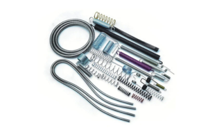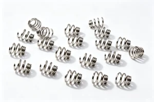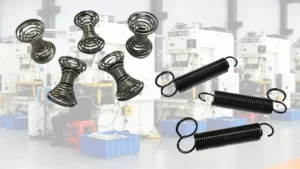
A compression spring is a mechanical spring designed to resist an axial compressive force. It typically consists of a helical coil that shortens when a load is applied, storing elastic potential energy and releasing it as the load is removed. Compression springs provide controlled return force, cushioning, contact pressure, or repeatable movement. Their performance depends on wire diameter, coil diameter, active coils, material, end configuration, spring rate, working deflection, and installation conditions—not on overall size alone. This guide covers how compression springs work, how their main dimensions and loads are evaluated, which types are available, what commonly causes selection failures, and how to choose a spring for a specific application. For OEM programs, see our custom compression springs.
Quick Definition: What Is a Compression Spring?
A compression spring is an elastic component that resists a force applied along its axis. Most use a helical coil made from round wire, although rectangular-wire and special designs are available. When compressed, the spring shortens and stores energy through elastic deformation; when the load is reduced, it expands toward its free length and returns energy to the mechanism.
Compression springs are among the most common spring configurations because they provide predictable force in a compact space. They appear in pens and switches, automotive assemblies, industrial tooling, valves, and precision equipment. Terminology and design requirements should be checked against applicable spring standards and technical guidance, such as publications from the Spring Manufacturers Institute (SMI), rather than relying on a generic description alone.
How Compression Springs Work
When an axial force pushes the ends toward each other, the coil wire twists and adjacent coils move closer. Within the intended elastic working range, this deformation stores energy. When the external force is reduced, the spring pushes back toward its free length.
For a spring operating within a suitable linear range, the load–deflection relationship follows Hooke’s law:
F = k × δ
Here, F is applied force, k is spring rate, and δ is deflection from free length. For example, a spring rate of 10 N/mm under 2 mm deflection produces approximately 20 N of load, assuming linear behavior and a correctly defined working range. Actual performance can differ because of tolerances, end seating, material behavior, and operating conditions.
Response is influenced by wire diameter, mean coil diameter, active coil count, material shear modulus, free length, and end style. A thicker wire generally increases spring rate substantially; more active coils generally reduce it. Installation also matters: poor alignment can introduce bending, friction, or wear that a simple axial calculation does not capture. A compression spring should therefore be evaluated as part of the assembly, not as an isolated component.
Core Design Parameters & Calculations
Selection starts with available space and required force, then checks whether the spring can travel through its operating range without buckling, reaching solid height, or exceeding allowable stress. These conditions are linked, so dimensions should be evaluated together rather than chosen independently.

Key Dimensions and Coil Geometry
- Wire diameter (d): Diameter of the wire forming the coil. It strongly affects rate and stress; small changes can produce noticeable force changes, so tolerances matter.
- Outside diameter (OD): Largest diameter across the coil. Critical when the spring fits inside a bore, counterbore, or housing; maximum OD must account for tolerance, movement, and lateral deflection.
- Inside diameter (ID): Open diameter inside the coil. Critical when installed over a guide rod or shaft; minimum ID must provide clearance for the guide, including dimensional variation and misalignment.
- Mean coil diameter (D): Average diameter along the wire centerline. For a round-wire cylindrical spring, D = (OD + ID) / 2, equivalently D = OD − d and D = ID + d.
- Free length (L0): Unloaded length. It determines available compression room and helps establish preload and working deflection; free length alone does not specify delivered force.
- Solid height (Ls): Approximate length when coils close against one another. It depends on wire diameter, total coils, and end configuration. The spring should not unintentionally reach solid height in normal operation.
- Total coils and active coils: Total coils include end coils; active coils contribute substantially to deflection. End design affects the difference, and active coil count is a key input to rate calculations.
- Pitch (p): Axial distance between corresponding points on adjacent coils. It affects available travel before coil contact and should be considered with free length, coil count, and solid height.
- Spring index (C): Ratio of mean coil diameter to wire diameter, C = D / d. A low index means a tight coil that is harder to manufacture and may concentrate stress; a high index creates a slender coil more prone to distortion. A value around 6–8 is a practical starting range, not a universal rule.
For a guided spring, check minimum ID against the guide’s maximum diameter. For a spring in a bore, check maximum OD against the bore’s minimum diameter. These are tolerance-stack questions: nominal dimensions that look compatible on a drawing may still interfere at worst-case limits.
Load, Rate, Deflection and Loaded Height
Spring rate is the change in force divided by the corresponding change in deflection, commonly expressed in N/mm, N/m, or lbf/in. A higher rate means more force is required for each unit of additional compression.
For a conventional round-wire helical compression spring, a common theoretical rate equation is:
k = Gd4 / (8D3n)
Here, G is shear modulus, d is wire diameter, D is mean coil diameter, and n is active coils. The equation shows the main relationships: wire diameter raises rate strongly because it is raised to the fourth power; larger mean coil diameter reduces rate; more active coils make the spring softer. It is a design model, not a substitute for validation of end conditions, material, geometry, and manufacturing tolerances.
Load at a given deflection is the force produced when the spring is compressed by a specified amount. In a linear range, load is approximately rate multiplied by deflection. When a design requires a particular force at a particular height, specify that force–height condition directly rather than relying only on free length and coil count.
Deflection is free length minus loaded height. If free length is 40 mm and working height is 32 mm, deflection is 8 mm. Loaded height is the spring’s length under a specified load or assembly condition. Both must be checked against solid height and required travel. A spring with the correct rate may still be unsuitable if it reaches coil contact before the mechanism completes its movement.
For first-pass design, calculate force at minimum and maximum working heights, then check the worst-case dimensional combination. Do not assume linear behavior all the way to solid height; as coils approach contact, force can rise sharply and damage the spring or transfer excessive load into the structure.
End Types and Solid Height Considerations
Open ends continue the helix without bringing end coils into close contact with the adjacent coil. They suit less demanding seating requirements but may not sit as squarely on a flat surface.
Closed ends bring end coils into contact with the neighboring coil, providing a more defined seating surface than open ends. Exact geometry and squareness still depend on specification and manufacturing process.
Closed and ground ends are closed ends ground to provide flatter, more parallel bearing surfaces. This improves seating and load alignment where stability matters. Grinding affects end geometry and should be reflected in specified solid height and overall design.
End configuration influences total coil count, solid height, seating, and force transfer into adjacent parts. Do not estimate solid height from wire diameter alone; confirm the manufacturer’s dimensional definition and leave clearance for tolerances, dynamic travel, and safety margin.
Buckling, Surging and Stress Considerations
Buckling is lateral deflection or bowing under axial compression. It becomes more likely with long, slender springs, poorly supported ends, or force misalignment. A guide rod, guide sleeve, better end support, or different geometry may improve stability, provided guide clearance is correctly designed.
Surging is dynamic coil oscillation along the spring length. If operating frequency approaches the spring’s natural frequency, noise, stress, and fatigue risk can increase. High-speed or cyclic applications may need dynamic analysis rather than static load calculation alone.
Stress and fatigue must be evaluated at maximum working load and across the expected load cycle. Spring wire experiences torsional stress as the coil deflects, and coil curvature creates stress concentration influenced by spring index. Repeated loading, corrosion, surface condition, temperature, and residual stresses affect service life. Allowable stress is not one fixed value: it depends on material, wire size, operating conditions, cycle requirements, and design method. Use an appropriate spring design reference or engineering calculation rather than treating a single percentage as universally safe.
Materials and Wire Cross-Sections
Carbon spring steel is widely used where cost, strength, and fatigue performance matter and the environment is suitable; it may need a protective finish if corrosion is a concern. Stainless spring steel is often considered for improved corrosion resistance, although grade depends on temperature, stress, exposure, and forming requirements. Alloy spring steels may be selected for particular strength, fatigue, or service requirements. Material selection should be based on the complete operating environment, not on price or material name alone.
Most general-purpose compression springs use round wire, which is versatile and widely available. Rectangular wire can provide a different combination of load capacity and space efficiency. Die springs commonly use rectangular-section wire because it supports high loads in compact tooling. However, rectangular wire does not automatically make a spring better: geometry, stress distribution, manufacturing capability, deflection, and available space must all be evaluated.
Also consider temperature, humidity, corrosive chemicals, cleaning agents, lubrication, surface treatment, and expected cycle count. A coating can improve corrosion resistance but may change dimensions or introduce process-specific risks. For high-cycle applications, confirm that material and finishing are compatible with the intended fatigue life. For custom wire forms and rectangular-wire components, see custom spring wire forms and rectangular wire components.
Common Mistakes and Failure Causes in Compression Spring Selection
Many compression spring problems come from a mismatch between the spring and its installation rather than from a material defect alone. The checks below connect common symptoms with likely causes and practical prevention. Numerical limits are preliminary guidance and should be verified for the actual spring, material, and operating conditions.
Installation Space, Guidance and Clearance
Symptom: The spring will not fit, rubs nearby components, tilts during compression, or wears prematurely. Likely cause: Bore, guide, lateral clearance, working height, or available travel were not checked as a tolerance stack; too little clearance causes rubbing or binding, while excessive clearance and poor support allow bowing. Prevention: Confirm the full installation envelope and effective compression travel. Decide whether the spring is located by OD in a bore or ID over a guide, and check worst-case clearances with suitable guidance and alignment. Where dynamic force and stress relaxation are concerns, elastic structural components that absorb dynamic force may be a better fit.

Diameter Basis and Tolerance Traps
Symptom: A spring matches nominal dimensions but will not fit over a shaft or inside a hole; parts from the same order show unexpected force variation. Likely cause: The design does not clearly define the controlling diameter and tolerance, or it overlooks rate sensitivity to wire diameter. In the rate equation, wire diameter is raised to the fourth power, so small dimensional changes can significantly affect rate. Prevention: State whether ID or OD controls the fit, define relevant tolerances, and specify load at a defined test height with an acceptable force tolerance, such as ±10% where appropriate. Verify that the tolerance is achievable and adequate.
Deflection, Travel and Solid Height Limits
Symptom: The spring loses force over time, takes a permanent set, or causes a sudden load increase at the travel limit. Likely cause: Working deflection is too large, the spring approaches solid height, or tolerance accumulation lets some units reach coil contact earlier. A 20–30% free-length deflection may help early estimation for static cases, but it is not a universal design limit. Prevention: Calculate minimum and maximum working heights, check solid height at worst-case tolerances, and preserve adequate travel margin. Validate actual stress and fatigue rather than relying on a percentage alone.
Allowable Stress, Spring Index and Fatigue
Symptom: A spring takes a set, breaks earlier than expected, or fails after repeated cycling despite having the required initial rate. Likely cause: The design checks stiffness but not maximum stress, stress range, fatigue life, corrosion, or spring index suitability. Very low index increases forming difficulty and stress concentration; very high index increases distortion and instability risk. Prevention: Evaluate stress using a recognized spring design method for the actual material, load cycle, and required life. Treat a spring index around 6–8 as a common starting range, not a guarantee. Include preload, solid-height limits, tolerances, and environmental effects.
Environment, Coating and Long-Term Set
Symptom: A spring loses force under sustained compression, corrodes in service, or fractures after surface treatment. Likely cause: Temperature, moisture, chemicals, sustained stress, or finishing-process effects were overlooked. Long-term stress relaxation or permanent set can reduce force, and some coating processes introduce risks depending on material and process controls. More expensive material is not automatically best. Prevention: Define temperature, humidity, chemical exposure, cycle count, and dwell time before choosing material and finish. For sustained compression, evaluate stress relaxation and set; for coated high-strength steel, confirm the finishing process is appropriate and controlled.
Failure Troubleshooting Order
Symptom: A failed spring is immediately blamed on material quality or the supplier, and replacements show the same problem. Likely cause: Troubleshooting starts with the part without checking installation and operating conditions. Prevention: Inspect in a consistent order: first confirm installation space, alignment, and guidance; next measure actual working height, travel, and loading cycle; then review temperature, corrosion, and surface treatment; finally reassess dimensions, material, stress, fatigue requirements, and specified load. Record failure location and conditions before changing the design.
Types of Compression Springs
Compression springs can be grouped by coil shape, end geometry, wire cross-section, and intended load or space requirements. The right type depends on the assembly envelope, required force and travel, lateral stability, manufacturing constraints, and service conditions. For space-constrained assemblies, custom wave springs for space-constrained assemblies may offer a practical alternative.
Straight Helical / Cylindrical Compression Springs
These have a generally constant coil diameter and are the most familiar compression spring form. They suit general-purpose applications needing predictable axial force where space can accommodate their solid height and stability requirements.
Conical Compression Springs
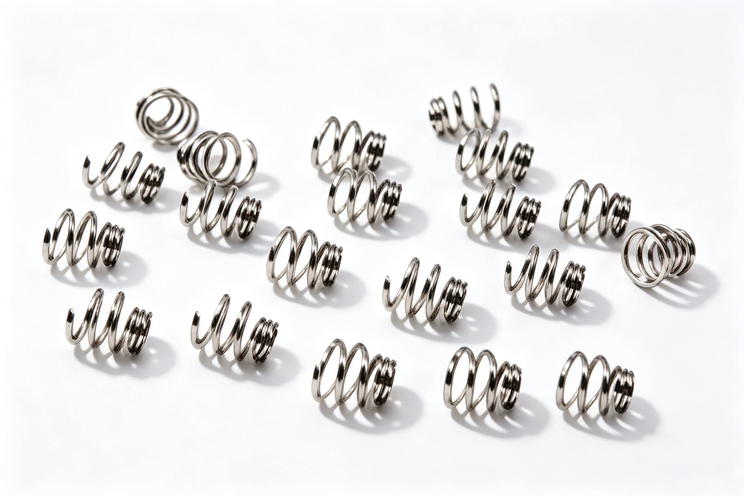
Coil diameter changes progressively from one end to the other. Coils may nest during compression, allowing lower solid height than a comparable cylindrical design in suitable configurations. Geometry can also improve stability in some installations, but load–deflection response and coil-contact sequence must be checked.
Barrel Compression Springs
Larger diameter near the middle and smaller toward the ends. This shape can provide lateral stability or fit a particular surrounding envelope. Useful when a straight cylindrical spring does not provide the desired support or geometry, but force behavior depends on dimensions and coil arrangement.
Hourglass Compression Springs
Smaller diameter around the center and larger near the ends. The reduced center affects lateral behavior and how the spring occupies space during compression. Selected for specific stability, packaging, or load-response requirements rather than as a universal replacement for cylindrical springs.
Reduced-End Compression Springs
Smaller-diameter coils at one or both ends. Reduced ends can help locate the spring in a seat or provide a particular contact arrangement. Check how end geometry affects seating, active coils, solid height, and load alignment.
Die Springs
Designed for demanding tooling, often with rectangular-section wire and compact, high-load construction. Commonly used in stamping dies, presses, and industrial tools requiring repeated compression and substantial force. Selection must account for the manufacturer’s rated working range, duty cycle, installation guidance, and safety requirements.
Mini / Precision Compression Springs
Small dimensions with tighter control of force, geometry, and consistency. Used in medical devices, electronics, instruments, switches, and compact mechanisms. Material, surface condition, cleanliness, and measurement methods may be especially important where space is limited or operating requirements are sensitive.
Non-Helical / Special Forms
Special forms can be developed for unusual space, force, or movement requirements. Specify these around the actual application and review with a spring designer or manufacturer rather than selecting by shape name alone.
Compression vs Extension Springs: What’s the Difference?
Compression and extension springs both store elastic energy, but they respond to opposite loading conditions. A compression spring is shortened by a pushing force and pushes back. An extension spring is lengthened by a pulling force and resists being stretched, commonly using hooks or loops at its ends. The two are not interchangeable unless the assembly is redesigned for different force directions and end requirements.
| Feature | Compression Spring | Extension Spring |
|---|---|---|
| Primary loading | Axial compression | Axial tension |
| Movement under load | Becomes shorter | Becomes longer |
| Typical end form | Open, closed, or closed and ground ends | Hooks, loops, or other tension attachments |
| Typical applications | Pens, valves, suspension mechanisms, switches, tooling | Return mechanisms, screen doors, counterbalances, tensioned linkages |
This article focuses on compression springs. A separate compression-versus-extension spring guide can provide a deeper comparison of design calculations, end configurations, and application-specific trade-offs. If your assembly requires tension, see custom extension springs with hooks and loops.
Common Applications and Uses
Compression springs are used wherever a mechanism needs to resist a pushing force, return a component to position, maintain contact, absorb movement, or provide a controlled load.
- Automotive: Suspension springs support vehicle loads and respond to road movement; smaller springs in seats, latches, and switches provide cushioning, return force, or contact pressure.
- Medical devices: Precision springs provide return force, positioning, or controlled movement in instruments and delivery mechanisms. Material, cleanliness, corrosion resistance, and regulatory requirements must match the device.
- Aerospace: Springs in instrument panel returns, valve actuation, latch mechanisms, and landing-gear-related assemblies provide reliable mechanical response under specified loads, temperatures, vibration, and qualification requirements.
- Consumer products: Ballpoint pens use small compression springs to extend or retract the writing mechanism; locks, appliances, and switches use springs for return force or contact maintenance.
- Industrial equipment: Compression springs support die tooling, fixtures, valves, clamps, and automation mechanisms. Load rating, working travel, cycle life, and resistance to misalignment are key selection factors.
- Electronics and precision instruments: Small springs provide tactile feedback, electrical contact pressure, positioning, or repeatable movement in compact assemblies. Dimensional consistency and force tolerance may be critical. For contact and terminal designs, see precision contacts and terminals for medical and electronic devices.
Across these industries, the application determines required load, travel, life, material, end geometry, and dimensional tolerance. A spring that works in a low-cycle consumer product may not suit a high-frequency industrial mechanism without additional analysis and validation.
How to Choose the Right Compression Spring
Start by defining what the spring must do in the actual assembly. A practical selection checklist includes:
- Required load: Define the force needed at one or more specified working heights.
- Available space: Set maximum OD, minimum ID, free length, and space available at the compressed condition.
- Working travel: Calculate deflection and verify the spring will not unintentionally reach solid height.
- Service life: Identify whether the load is static, intermittent, or cyclic, and estimate required cycles.
- Environment: Specify operating temperature, moisture, chemicals, corrosion exposure, and cleaning requirements.
- Material and finish: Choose a suitable wire material and surface treatment for the loads and environment.
- Ends and guidance: Select an end style and determine whether the spring needs a guide rod, bore, or other support.
- Tolerances and inspection: Specify the controlling diameter, critical dimensions, and load at a defined test height with an appropriate tolerance.
Do not select by dimensions alone. Confirm spring rate and force at working height, solid-height clearance, buckling risk, dynamic surging risk where relevant, allowable stress, and the correct diameter tolerance basis. If the spring will operate at high frequency, near maximum deflection, or in a demanding environment, request an engineering review and test it in a representative assembly.
Use a spring selection tool or dimensional specification sheet to organize initial requirements, then provide load, travel, space limits, operating conditions, and expected life to a spring manufacturer or engineer. These details make it easier to evaluate a standard spring or develop a custom design with a custom precision spring manufacturer for OEM applications.
FAQ
What is a compression spring used for?
A compression spring resists a pushing force and returns energy as the force is reduced. Typical uses include pens, valves, switches, suspension mechanisms, tooling, clamps, and precision instruments. The exact design depends on force, travel, space, operating environment, and required service life.
How does a compression spring work?
An axial force pushes the ends together, reducing length and storing elastic energy in the wire. When the force is reduced, the spring expands toward free length. Within a suitable linear range, force is approximately spring rate multiplied by deflection.
What are the main types of compression springs?
Common types include straight helical or cylindrical, conical, barrel, hourglass, reduced-end, die, and miniature precision springs. They differ in coil geometry, end form, wire cross-section, stability, and available solid height. The application determines which design is suitable.
What is the difference between a compression spring and an extension spring?
A compression spring is shortened by a pushing force and resists compression. An extension spring is lengthened by a pulling force and resists tension. Compression springs commonly use open, closed, or ground ends, while extension springs often use hooks or loops. Their load directions and attachment requirements differ.
What materials are compression springs made of?
Common materials include carbon spring steel, stainless spring steel, and selected alloy spring steels. The appropriate material depends on strength, fatigue performance, temperature, corrosion exposure, manufacturing requirements, and cost. Surface treatment may be needed, but suitability should be checked for the material and application.
What is spring rate in a compression spring?
Spring rate is the force required to produce a unit of deflection, often expressed in N/mm or lbf/in. For a linear spring, it describes the slope of the load–deflection relationship. Wire diameter, mean coil diameter, active coil count, and material properties all affect rate.
How do you choose a compression spring?
Define required force at working height, available installation space, working travel, service life, environment, material, end style, and guidance. Then check spring rate, solid height, stress, fatigue, buckling, and relevant tolerances. For demanding or high-cycle applications, validate with engineering calculations and testing.
Why does my compression spring lose force or fail early?
Possible causes include excessive working stress, reaching solid height, fatigue, corrosion, stress relaxation during sustained compression, poor alignment, buckling, or unsuitable material or finish. Inspect installation and actual working travel first, then review load cycle, environment, dimensions, and material specification before changing the spring or supplier.
Next Step: Choose the Right Compression Spring for Your Application
A compression spring stores and releases elastic energy to resist axial compression, but reliable performance depends on matching geometry, spring rate, working deflection, material, end configuration, and tolerances to the application. Check installation clearance and guidance, avoid unintended solid-height contact, and assess stress, fatigue, environment, and dynamic behavior where relevant. Use a spring selection tool, review the applicable specification data, or contact Hershey Spring — custom spring manufacturer since 2000 to confirm the design and request a quote for a spring that meets your operating requirements.