Choose linear bearings for simpler, cost-sensitive motion systems. Choose profiled linear guides when the machine needs higher rigidity, greater load capacity, or more accurate positioning. The difference affects more than component selection. It determines how much machining the mounting base needs, how accurately the assembly must be aligned, and how much the system costs to maintain.
A round-shaft system may work perfectly well on a light-duty packaging machine. The same arrangement could cause excessive deflection on a CNC machine, where cutting forces act on the moving carriage. Replacing it with profiled guides may solve the rigidity problem, but it also introduces tighter mounting requirements and additional machining costs.
To make the right choice, just like you would compare component types in any mechanical design, evaluate four things: contact geometry, mechanical performance, installation requirements, and total cost of ownership (TCO).
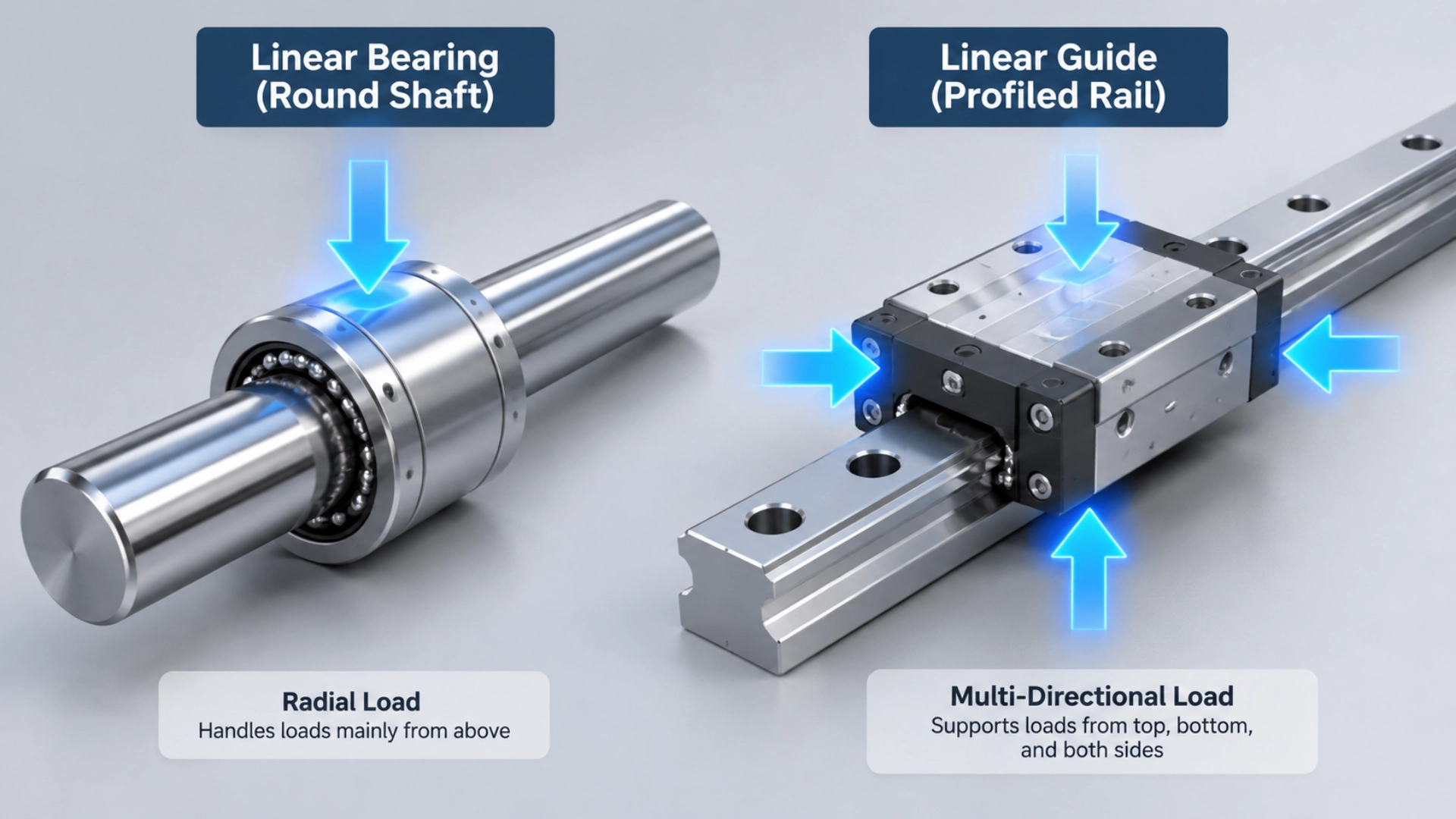
The Core Structural Difference: Round Shaft vs. Profiled Rail
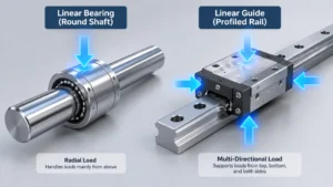
The main difference lies in how the rolling elements contact the track. Linear bearings run along cylindrical shafts. Linear guides use shaped raceways built into a profiled rail and carriage. This changes how each system transfers loads and resists forces.
Linear Bearings (Round Shafts): Point and Line Contact
A typical ball-type linear bearing contains an outer housing, recirculating steel balls, and an internal ball-return circuit. The balls roll between the bearing and a hardened cylindrical shaft as the carriage moves.
The contact areas are relatively small. Under load, the balls and raceway surfaces deform elastically, creating localized contact stresses.
This arrangement handles straightforward radial loading well, but it offers limited resistance to twisting and overturning moments. Consider a moving platform carrying a motor mounted above the shaft centerline. The offset creates a moment that tends to rotate the platform. A single round shaft cannot resist that moment as effectively as a properly configured profiled guide.
Engineers often use two parallel shafts with multiple bearing blocks to improve stability. The distance between the shafts creates a wider support base and helps resist rotation.
- Contact geometry: Recirculating balls contact a cylindrical shaft through small localized contact areas.
- Load behavior: Primarily designed for radial loads.
- Moment resistance: Usually requires multiple shafts or a wider bearing arrangement.
- Typical advantage: Simple construction, accessible components, and relatively forgiving installation requirements.
Linear Guides (Profiled Rails): Gothic Arch and Face Contact
Profiled linear guides consist of a precision-machined rail and a matching carriage containing recirculating balls or rollers. The rolling elements travel through shaped raceways rather than along a cylindrical surface.
Many four-row ball guides use a Gothic arch raceway profile. The geometry creates multiple contact angles between the balls and raceways, allowing the carriage to support loads from four principal directions.
When a downward force acts on the carriage, one set of contact regions transfers the load into the rail. When a horizontal force acts from the side, other contact regions carry it. This arrangement also helps the guide resist pitching, rolling, and yawing moments.
Roller-type guides use cylindrical rollers instead of balls. Their larger contact areas can provide higher rigidity and load capacity in suitable applications, although they require careful attention to alignment and lubrication.
The practical difference is clear: a properly selected profiled guide can handle vertical and lateral loads within one compact rail-and-carriage assembly. Multiple rails and carriages can be added when the machine needs greater moment resistance.
- Contact geometry: Multiple rows of balls or rollers run through precision-shaped raceways.
- Load behavior: Supports loads from multiple directions, depending on the guide design.
- Moment resistance: Raceway geometry and carriage spacing provide resistance to overturning forces.
- Typical advantage: High rigidity, compact construction, and accurate positioning.
Gothic arch raceways are common in four-row ball guides, but not every profiled guide uses the same geometry. Always check the manufacturer’s directional load and moment ratings before selecting a model.
Performance Head-to-Head: 6 Critical Parameters
For machine design, the most useful comparison covers load capacity, rigidity, accuracy, friction, speed, and contamination tolerance. These parameters determine whether a system can handle the actual operating conditions rather than simply move along a straight path.
| Parameter | Linear Bearings (Round Shaft) | Linear Guides (Profiled Rail) |
|---|---|---|
| Load Capacity | Generally suited to light and medium loads. Supported shafts can handle higher loads by reducing shaft deflection. | Available for medium to very high loads, depending on rail size, carriage length, and rolling element type. |
| Rigidity | Limited by shaft bending, bearing clearance, and support spacing. | Generally higher due to multiple raceway contact rows and preload options. |
| Accuracy | Suitable for general-purpose positioning. System accuracy often falls around 0.05–0.1 mm in less demanding configurations. | Precision grades can achieve micrometer-level running accuracy under suitable installation and operating conditions. |
| Friction | Low rolling resistance, with performance affected by seals, lubrication, and shaft condition. | Also offers low rolling resistance. Preload and sealing can increase the force needed to move the carriage. |
| Speed | Suitable for many general-purpose linear motion applications. Maximum speed depends on bearing design and lubrication. | Supports high-speed industrial motion when the guide, lubrication, and operating conditions are correctly specified. |
| Contamination Tolerance | Open shaft surfaces are relatively easy to inspect and clean, although exposed balls still need protection. | Raceways and recirculation circuits require effective seals, lubrication, and protection from chips and abrasive particles. |
Note: These are general engineering comparisons, not guaranteed product specifications. Actual performance depends on dimensions, preload, shaft or rail support, mounting accuracy, lubrication, and manufacturer ratings. Positioning accuracy, repeatability, and running parallelism are also different measurements.
Rigidity & Load Capacity
Rigidity determines how much the moving assembly deflects under an applied force. On a CNC machine, that deflection can shift the cutting tool relative to the workpiece. On an automated inspection system, it can move a sensor away from its intended measurement position.
Profiled guides generally provide higher rigidity because their rolling elements contact multiple raceway surfaces. Four-row ball guides distribute loads across several contact regions. Roller guides can provide even greater stiffness in suitable configurations because their rolling elements have larger contact areas.
Preload also matters. It introduces a controlled internal load between the rolling elements and raceways, reducing internal clearance before the guide carries its working load.
Take a milling machine as an example. When the cutting force changes direction, a guide with excessive clearance may allow the carriage to shift slightly. A properly preloaded guide limits that movement and helps maintain tool position.
Round-shaft bearings can also be supplied with different clearance or preload conditions. However, their overall rigidity depends heavily on shaft diameter, unsupported span, support spacing, bearing length, and frame stiffness.
In some configurations, a profiled guide system can be an order of magnitude stiffer than a comparable round-shaft arrangement. This is not a universal ratio. Compare the actual system stiffness and moment ratings rather than relying on a general rule.
Accuracy & Repeatability
Accuracy describes how closely the actual position matches the commanded position. Repeatability describes how consistently the system returns to the same position over multiple movements.
Running parallelism is another important factor. It measures how closely the carriage follows the intended straight-line path along the travel distance.
For general-purpose round-shaft systems, positioning accuracy around 0.05–0.1 mm may be sufficient. This is a practical reference, not a fixed specification. Shaft straightness, bearing clearance, mounting alignment, and the drive system all affect the final result.
Profiled linear guides are available in several accuracy grades. High-precision versions can achieve deviations in the micrometer range, depending on rail length, guide class, and installation conditions.
This matters when a machine must position a cutting tool, dispensing head, or inspection probe repeatedly within a narrow tolerance window.
However, a precision guide cannot compensate for a flexible machine frame or inaccurate drive system. The mounting base, ball screw or belt drive, encoder, thermal behavior, and assembly process must all support the required positioning accuracy.
Friction & Smoothness
Both systems use rolling elements to reduce resistance during movement. Neither relies on the sliding contact found in a conventional plain bearing or bushing.
Round-shaft bearings often provide smooth movement with relatively low resistance. Their actual running force depends on bearing clearance, seals, lubrication, shaft finish, and applied load.
Profiled guides can also move smoothly, but preload increases the internal contact force between the rolling elements and raceways. A highly preloaded carriage may therefore require more driving force than a clearance-fit version of the same guide.
At low speeds, poor lubrication, incorrect preload, or misaligned rails can cause uneven running resistance. If the drive system cannot compensate for these variations, the carriage may move unevenly or exhibit stick-slip behavior.
Stick-slip is not an unavoidable feature of preloaded linear guides. It can also result from poor installation, friction fluctuations, or unsuitable drive control.
When comparing friction, check the actual operating load, speed, preload, and seal configuration. A slightly higher running force may be a reasonable trade-off for better positioning stability under load.
The Hidden Cost: Installation Tolerance and Base Machining
The mounting base can change the cost comparison more than the bearing itself. Round-shaft systems are generally easier to install on fabricated frames. Profiled guides need more accurate reference surfaces and closer alignment.
Linear Bearings: High Tolerance for Base Imperfections
Round-shaft bearings are often suitable for welded steel frames, aluminum extrusions, and other structures that are difficult or expensive to machine precisely.
For example, a light-duty packaging machine may use two parallel shafts mounted to an aluminum extrusion frame. If the machine only moves small components and does not require high positioning accuracy, the frame may not need the same machining precision as a CNC machine base.
Some round-shaft arrangements can accommodate mounting deviations on the order of 150 μm/m or more. The permissible deviation depends on shaft support design, bearing alignment, self-aligning features, and required performance. It is not a universal tolerance for linear bearings.
The main installation advantages are:
- Less demanding mounting-surface preparation in suitable applications.
- Compatibility with standard aluminum extrusion structures.
- Lower machining requirements for welded and fabricated frames.
- Relatively straightforward component replacement.
- More flexibility when designing budget-sensitive equipment.
That does not mean alignment is optional. Shaft parallelism, straightness, and support spacing still affect running resistance and bearing life. A poorly aligned round-shaft system can bind just as easily as a poorly installed guide.
Linear Guides: The “Zero-Tolerance” Rule
Profiled linear guides depend on accurate mounting surfaces. If the base is twisted, uneven, or incorrectly aligned, the carriage may experience internal forces that were not part of the original design.
Consider two rails installed on a machine base with a slight twist. A rigid platform connects the carriages. As the platform moves, the rails force the assembly to follow two paths that are not properly aligned.
This can cause:
- Higher running resistance and uneven movement.
- Abnormal noise during travel.
- Uneven load distribution across the rolling elements.
- Accelerated raceway wear.
- Reduced positioning accuracy and premature failure.
Manufacturers specify mounting requirements for surface flatness, rail straightness, reference shoulders, and parallelism. The required accuracy depends on the guide size, precision grade, preload, and machine application.
Depending on these requirements, the mounting base may need milling or grinding. Reference shoulders and mounting holes may also need precision machining.
These operations add cost before the guides are installed. They also increase assembly and inspection time.
There is no literal zero-tolerance rule for profiled guides. The correct approach is to follow the manufacturer’s installation limits for the selected model. The tighter the machine’s positioning and rigidity requirements, the more attention the mounting geometry needs.
For machine builders, the real comparison is the total installation cost: base machining, alignment, fastening, inspection, and assembly labor. If your team lacks in-house machining resources, consider reviewing outsourcing options for precision components early in the design phase.
Application Selection Guide: Which Should You Choose?
Choose the system that meets the machine’s actual load and accuracy requirements without adding unnecessary machining or component costs.
When to Choose Linear Bearings
Round-shaft linear bearings are suitable when the machine needs straightforward movement, moderate load capacity, and general-purpose positioning accuracy.
They make sense when the structure is simple and precision machining would add cost without improving the finished machine’s performance.
Typical applications include:
- 3D printers: Many desktop printers use round-shaft bearings for lightweight moving assemblies where extreme rigidity is unnecessary.
- Light-duty material handling: Suitable for small transfer platforms and simple pick-and-place mechanisms with predictable loads.
- DIY automation: Useful for prototypes and low-volume equipment built around aluminum extrusion frames.
- Packaging equipment: Suitable for auxiliary sliding mechanisms that do not experience substantial cutting or impact forces.
- Inspection fixtures: Practical for manually adjusted or lightly loaded positioning assemblies.
Round-shaft systems are also attractive when standard shaft diameters and bearing housings are readily available. This simplifies sourcing and replacement.
If the application involves heavier loads, consider a supported shaft rather than assuming an unsupported shaft can carry the same load. The support structure reduces shaft deflection, but the complete assembly still needs to be checked for load capacity and moment resistance.
When to Choose Linear Guides
Profiled linear guides are the better choice when the moving assembly must resist substantial forces, maintain accurate positioning, or support loads from multiple directions.
Typical applications include:
- CNC machine tools: Resist cutting forces and maintain tool positioning during machining.
- Heavy-duty gantry systems: Support large moving assemblies and resist overturning moments from offset loads.
- Industrial automation: Provide stable movement for robotic stages, transfer equipment, and automated production lines.
- Precision inspection machines: Maintain repeatable positioning for optical sensors and measurement probes.
- Heavy-load assembly equipment: Support fixtures and tooling exposed to changing forces during production cycles.
Profiled guides are particularly useful when the machine needs high load capacity within a relatively compact footprint. A properly configured rail-and-carriage system can provide the rigidity that would otherwise require a more complicated round-shaft arrangement.
The TCO Illusion: Why a More Expensive Guide Can Cost Less
A cheaper component does not always produce a cheaper machine. Total Cost of Ownership includes the purchase price, installation, maintenance, downtime, replacement parts, and losses caused by poor positioning performance.
Consider a CNC machine designed with round-shaft bearings to reduce its initial BOM cost. During cutting, the moving platform deflects under tool forces. The resulting dimensional variation leads to repeated adjustments, additional inspection, and rejected parts.
The bearings may have cost less, but the savings disappear if the machine cannot consistently produce parts within tolerance.
Now consider a profiled guide system. It costs more and may require a machined mounting base, but its higher rigidity helps control carriage deflection under working loads.
Compare the following cost categories before making the decision:
- Component cost: Rails, shafts, carriages, bearing blocks, and mounting hardware.
- Installation cost: Base machining, alignment, assembly labor, and inspection.
- Maintenance cost: Lubrication, cleaning, replacement parts, and technician time.
- Downtime cost: Lost production during troubleshooting and component replacement.
- Quality cost: Scrap, rework, additional inspection, and reduced production yield.
For a desktop 3D printer, paying extra for a high-rigidity guide may not produce a meaningful return. For a CNC machine, the cost of rejected parts and production interruptions may exceed the price difference between the two systems.
The practical rule is simple: select the least expensive system that consistently meets the machine’s load, rigidity, accuracy, and service-life requirements. Do not pay for performance the machine does not need, but do not save money on a component that limits the entire machine.
Common Mistakes and Migration Scenarios
Correct component selection is only half the job. The bearing arrangement, mounting geometry, and surrounding machine structure must also work together.
The “Over-constraining” Mistake
A common round-shaft arrangement uses two parallel shafts and four bearing blocks connected to one moving platform. The design is straightforward, but it can become over-constrained if the shafts are not parallel.
For example, a welded frame may distort slightly during fabrication. The two shafts may appear aligned before tightening, but their relative positions can change when the mounting bolts are secured.
Because all four bearing blocks are attached to the same rigid platform, they cannot easily follow different travel paths. The result may be:
- Increased resistance as the platform moves.
- Uneven loading across the bearing blocks.
- Localized wear on the shafts and ball circuits.
- Binding at specific points along the travel path.
- Higher motor loads and inconsistent movement.
To prevent this, establish one shaft as the reference and align the second shaft during installation. Where the bearing design permits it, suitable self-aligning or floating arrangements can also reduce sensitivity to small alignment errors.
Switching to profiled guides may simplify the support arrangement in some applications. However, two rails mounted on an inaccurate base can create the same problem. A guide upgrade does not eliminate the need for correct alignment.
Upgrading from Bearings to Guides
Replacing round-shaft bearings with profiled guides can improve rigidity and positioning performance, but the two systems have different mounting dimensions. A direct replacement is rarely possible without modifying the machine structure.
Before converting an existing machine, check these items:
- Mounting footprint: Measure the original shaft spacing, bearing positions, and available mounting width. Compare them with the selected rail and carriage dimensions.
- Carriage height: A profiled guide carriage may sit higher or lower than the original bearing block, changing the position of the moving platform.
- Mounting hole pattern: Check rail bolt spacing, carriage mounting holes, thread sizes, and tool access.
- Reference surfaces: Inspect the existing frame for flatness and straightness. Milling or grinding may be necessary.
- Rail parallelism: Establish a reference rail and align additional rails according to the manufacturer’s installation procedure.
- Load and moment ratings: Recalculate applied forces and overturning moments. Do not select a guide based only on the original bearing’s nominal load rating.
- Drive compatibility: Check whether the motor, ball screw, belt, or actuator can handle the new system’s friction and acceleration requirements.
- Lubrication and protection: Review lubrication intervals, seals, covers, and contamination protection.
Start with the machine’s operating conditions, not just the dimensions of the original bearings.
If the original problem is platform deflection during machining, installing a larger guide may not solve it if the frame itself is flexible. The mounting base, carriage spacing, and load application point must also be evaluated.
If the original system binds because the shafts are misaligned, replacing the bearings without correcting the frame geometry can reproduce the same problem.
A reliable conversion therefore requires a complete review of the linear motion assembly, including load calculations, mounting geometry, guide sizing, and alignment.
FAQs
Are linear guides better than linear bearings?
Profiled linear guides generally offer higher rigidity, greater load capacity, and better positioning accuracy. They are usually the better choice for CNC machines, heavy-duty automation, and precision positioning equipment.
Round-shaft linear bearings are often more economical and easier to install. They work well in light-duty machines and applications where moderate accuracy is sufficient.
The right choice depends on load, positioning requirements, mounting conditions, and total cost of ownership. A more expensive guide is not automatically the better investment.
Can I use a linear bearing on a supported shaft for heavy loads?
Yes. A supported shaft can carry higher loads than an unsupported shaft of the same diameter because the support reduces bending along the travel length.
An unsupported shaft is usually supported at its ends. A load applied near the center can cause significant deflection, especially when the distance between supports is large.
A supported shaft uses a continuous or near-continuous mounting support underneath the shaft. This reduces bending and improves the stiffness of the assembly.
For example, a long material-handling axis may use supported shafts to limit deflection across the working span.
However, shaft support does not automatically give a round-shaft system the same moment resistance or rigidity as a profiled guide. The complete assembly must still be checked for:
- Dynamic and static bearing load ratings.
- Shaft diameter and allowable deflection.
- Support strength and mounting spacing.
- Applied moments and load distribution.
- Required service life and operating speed.
If the machine also requires high positioning accuracy or substantial resistance to overturning moments, a profiled linear guide may be the more suitable solution.
Final Thoughts
Linear bearings are a practical choice for simple, cost-sensitive motion systems. Profiled linear guides are better suited to machines that need higher rigidity, multi-directional load support, and accurate positioning under working loads.
Before selecting either system, check the complete assembly. Shaft or rail support, mounting tolerances, alignment, drive requirements, maintenance, and downtime all affect the final cost.
The best solution is not necessarily the most expensive one. It is the system that meets the machine’s actual performance requirements without adding unnecessary machining, complexity, or maintenance costs.
Need help sizing a linear motion system?
Calculating moment loads, choosing the right preload, or designing the mounting base can be complex. Our engineering team provides free technical consultation to help you match the right bearing or guide to your machine’s specific requirements.