Choosing the wrong spindle bearing can lead to excessive heat, spindle runout, poor surface finish, and unplanned machine downtime. The right choice depends on more than bearing dimensions. Contact angle, preload, rotational speed, lubrication, and mounting accuracy all affect spindle performance. This guide compares four types of machine tool spindle bearings, explains the engineering factors behind selection, and shows how to prevent common bearing failures during operation and rebuilds.
1. What Makes Spindle Bearings Different from Standard Bearings?
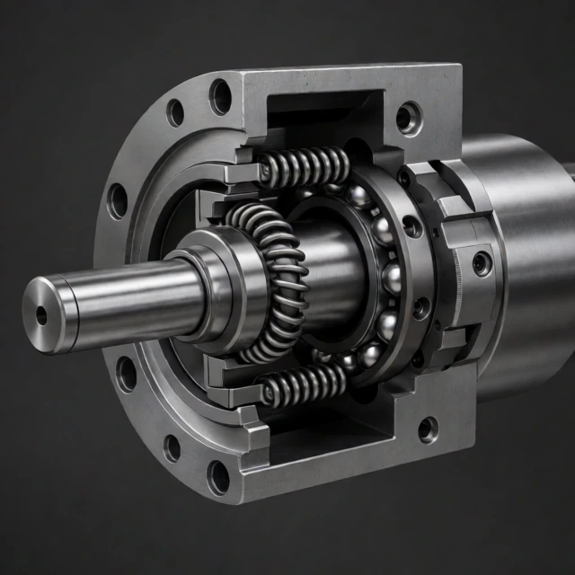
Machine tool spindle bearings must maintain shaft accuracy under high rotational speeds, cutting forces, and changing temperatures. A general-purpose bearing may support the load, but that does not mean it can maintain the runout, rigidity, and thermal stability required by a CNC spindle.
Consider a milling spindle running at 20,000 RPM. Even a small change in bearing clearance or temperature can affect tool positioning. During machining, that movement may show up as vibration, dimensional errors, or an inconsistent surface finish.
The difference comes down to three performance requirements: running accuracy, rigidity, and speed. They must work together.
The Three Requirements of Spindle Performance: Accuracy, Rigidity, and Speed
These three characteristics determine how a spindle behaves under actual machining conditions. Improving one does not always improve the others, so bearing selection requires a balance.
Running Accuracy
Running accuracy describes how closely the rotating spindle follows its intended axis. Bearing geometry, raceway accuracy, rolling element quality, mounting fits, and assembly conditions all contribute to this performance.
For example, a grinding spindle with excessive radial runout may produce uneven material removal. In high-precision milling, the same problem can cause dimensional variation between machined surfaces.
High-precision spindle bearings reduce bearing-related rotational errors, but they cannot correct inaccuracies in the shaft, housing, or tool assembly.
Rigidity
Rigidity describes how much the spindle shaft moves when cutting forces act on it. A rigid bearing arrangement keeps the tool in position and reduces deflection during machining.
This matters most when cutting forces are high. During heavy milling or boring, insufficient radial stiffness can cause tool displacement, chatter, and dimensional errors.
Bearing type, contact angle, preload, roller geometry, and the distance between bearing supports all affect spindle rigidity.
Rotational Speed
At high RPM, rolling elements experience greater centrifugal forces. Friction also generates heat, which can change bearing dimensions and operating preload.
If the temperature continues to rise, the spindle may experience thermal growth, increased vibration, and premature bearing wear.
High-speed spindle bearings therefore need suitable internal geometry, cage design, lubrication, and cooling. Hybrid ceramic bearings are often used because their silicon nitride balls have lower density than steel balls.
Why Standard Deep Groove Ball Bearings Are Not a Direct Replacement
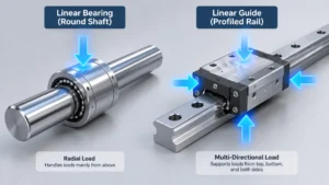
Standard deep groove ball bearings work well in motors, pumps, and many general-purpose machines. However, their specifications may not meet the requirements of a precision CNC spindle. Similar to how different linear bearing and guide systems serve distinct motion profiles, spindle bearings require a specialized design approach.
There are four main reasons.
- Running accuracy: General-purpose tolerance classes may allow more dimensional and rotational variation than a precision spindle can tolerate.
- Internal clearance: Standard internal clearance may not provide the controlled operating conditions required by a preloaded spindle assembly.
- Speed capability: Cage design, lubrication, internal geometry, and heat generation may limit permissible operating speed.
- Axial positioning and rigidity: A standard deep groove bearing may not provide the stiffness and controlled axial support required by the spindle design.
This does not mean deep groove bearings can never be used in a spindle. Specialized high-precision designs exist. The problem is treating a general-purpose bearing as an equivalent replacement simply because its bore, outside diameter, and width match the original component.
For a spindle rebuild, the replacement must meet the original bearing specification or have its suitability confirmed through engineering evaluation.
2. Four Types of Bearings Used in Machine Tool Spindles: Pros and Cons
The four bearing categories most relevant to machine tool spindle selection are angular contact ball bearings, cylindrical roller bearings, hybrid ceramic bearings, and thrust bearings. Each handles a different combination of speed, load, and stiffness requirements.
The important distinction is how each bearing transfers force through its rolling elements. That determines where it performs well and where another bearing type is needed.
Angular Contact Ball Bearings (ACBB): The High-Speed Workhorse
Angular contact ball bearings are widely used in CNC spindles because they support both radial and axial loads. They are particularly useful when the spindle must rotate quickly while maintaining accurate axial positioning.
The contact angle is one of the first specifications to check. Common spindle bearing designs use 15° or 25° contact angles, and the difference affects axial load capacity, rigidity, and speed capability.
15° vs. 25° Contact Angle
A 15° contact angle is generally favored when high rotational speed is a priority. It provides lower axial load capacity than a comparable 25° design but is commonly used in high-speed spindle arrangements.
A 25° contact angle provides greater axial load capacity and generally higher axial stiffness under comparable conditions. It can be useful when cutting operations generate heavier axial forces.
| Parameter | 15° Contact Angle | 25° Contact Angle |
|---|---|---|
| Axial load capacity | Relatively lower | Relatively higher |
| Axial rigidity | Relatively lower | Relatively higher |
| Speed suitability | Commonly favored for high-speed designs | Depends on bearing design and operating conditions |
| Typical application | High-speed milling and grinding | Spindles requiring greater axial support |
These are general design tendencies, not fixed performance limits. Bearing dimensions, ball size, cage design, preload, and lubrication also determine the actual permissible speed and load capacity.
Single-Row and Double-Row Arrangements
Single-row angular contact bearings are commonly installed in matched pairs or sets. Their arrangement determines how they support axial forces.
- Back-to-back (DB): The contact lines diverge outward. This creates a wider effective support span and provides good resistance to overturning moments.
- Face-to-face (DF): The contact lines converge inward. This arrangement accommodates some shaft and housing misalignment better than a back-to-back arrangement but generally offers lower moment rigidity.
- Tandem (DT): Both bearings support axial loads in the same direction. An additional opposing bearing arrangement is needed to support loads in the other direction.
Double-row angular contact bearings combine two rows of balls in one bearing. They can support radial loads and axial loads in both directions while occupying less axial space than some paired arrangements.
However, a double-row design is not automatically interchangeable with a matched single-row spindle bearing set. Speed capability, preload, and internal geometry must be checked.
Best suited for: High-speed CNC milling, machining centers, precision drilling, and grinding spindles requiring combined radial and axial support.
Cylindrical Roller Bearings (CRB): For Maximum Radial Rigidity
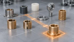
When radial cutting forces are the main concern, cylindrical roller bearings are often a better choice than ball bearings. Their line-contact geometry allows them to carry high radial loads with relatively low elastic deformation. This is a different wear dynamic compared to sliding contact bushings, which rely on a fluid film or solid lubricant.
During heavy turning or boring, the cutting tool pushes against the workpiece and creates radial forces on the spindle. Cylindrical roller bearings help resist the resulting shaft displacement.
Why Cylindrical Roller Bearings Provide High Radial Stiffness
Unlike ball bearings, which use point contact, cylindrical roller bearings distribute the load along a line of contact. This provides a larger effective contact area and generally higher radial load capacity under comparable design conditions.
The limitation is axial loading. Standard cylindrical roller bearings are not designed to carry significant axial forces. They are therefore commonly combined with angular contact ball bearings in spindle assemblies.
Single-Row vs. Double-Row Cylindrical Roller Bearings
Single-row cylindrical roller bearings provide high radial capacity within a relatively compact bearing width. They are suitable when the spindle design requires radial support without excessive axial space.
Double-row designs provide greater radial load capacity and stiffness. They are commonly considered for heavy-duty machine tool spindles.
Internal designs also matter. N and NU configurations generally allow axial displacement between the rings, while NJ and NUP arrangements provide different levels of axial locating capability.
These differences determine whether a bearing acts as a floating support or contributes to axial positioning. Check the complete bearing designation before selecting a replacement.
Best suited for: Heavy-duty turning, boring machines, large machining centers, and applications with substantial radial cutting forces.
Hybrid Ceramic Bearings: A Solution for High-Speed Spindles
Hybrid ceramic bearings combine steel inner and outer rings with silicon nitride (Si₃N₄) balls. Their main advantage in high-speed applications is the lower density of ceramic rolling elements compared with steel balls.
At high RPM, that difference becomes important.
How Silicon Nitride Balls Reduce Centrifugal Loading
As a bearing rotates, centrifugal forces act on the rolling elements. Heavier steel balls generate greater centrifugal forces at the same rotational speed and geometry.
Silicon nitride balls are considerably lighter. This reduces centrifugal loading on the outer raceway and helps control internal friction at high speeds.
Hybrid ceramic bearings offer several practical advantages:
- Lower rolling element mass: Reduces centrifugal forces during high-speed operation.
- Reduced friction-related heating: Can lower some rolling and sliding losses under suitable operating conditions.
- High hardness: Silicon nitride offers strong resistance to wear and deformation.
- Electrical insulation: Ceramic balls help prevent electrical current from passing through the rolling contacts.
- High-speed capability: Can provide higher permissible speeds than comparable all-steel designs, depending on the complete bearing configuration.
There are limits. Ceramic balls do not eliminate heat generated by raceway friction, cage interaction, lubricant churning, or excessive preload.
They also cost more than many conventional all-steel alternatives. For a spindle operating at moderate speed, the additional expense may not produce a meaningful performance benefit.
Best suited for: High-speed milling, precision grinding, high-speed machining centers, and applications where rolling element centrifugal forces and thermal stability are major concerns.
Thrust Bearings: Handling Axial Loads
Thrust bearings are designed to support forces acting parallel to the shaft axis. They are useful when a machine generates substantial axial loads that the primary radial bearing arrangement cannot adequately handle.
Two common designs are thrust ball bearings and thrust cylindrical roller bearings. Their main difference is the balance between speed and axial load capacity.
Thrust Ball Bearings
Thrust ball bearings use balls running between shaft and housing washers. They are suitable for axial loading where operating speed and load remain within the bearing’s specified limits.
However, conventional thrust ball bearings have limited radial load capacity. They also require appropriate axial loading to maintain stable rolling contact.
Thrust Cylindrical Roller Bearings
Thrust cylindrical roller bearings use rollers instead of balls. Their line-contact geometry allows them to support higher axial loads and provide greater axial rigidity under comparable conditions.
The trade-off is speed. Their operating speed is generally lower than that of many precision thrust ball bearing designs.
In spindle applications, thrust bearings must be evaluated alongside the main radial support system. Axial positioning, lubrication, mounting arrangement, and permissible speed all affect the final design.
| Bearing Type | Main Strength | Main Limitation | Typical Application |
|---|---|---|---|
| Angular Contact Ball | Combined radial and axial support | Load and speed depend on contact angle and arrangement | High-speed CNC spindles |
| Cylindrical Roller | High radial load capacity and stiffness | Standard designs cannot support significant axial loads | Heavy-duty turning and boring |
| Hybrid Ceramic | Lower rolling element mass and high-speed performance | Higher cost and application-specific requirements | High-speed precision machining |
| Thrust Bearing | Dedicated axial load support | Limited radial load capability | Axially loaded spindle assemblies |
3. Beyond Bearing Types: Engineering Constraints for CNC Spindle Selection
Identifying the bearing type does not complete the selection process. Two angular contact bearings with the same dimensions can produce different spindle performance because of differences in preload, lubrication, precision, and mounting conditions.
These factors become especially important when a spindle must operate at high speed for extended periods or maintain tight machining tolerances.
The Preload Paradox: Rigidity vs. Heat
Preload improves spindle stiffness, but too much preload generates frictional heat and can shorten bearing life. The correct setting is the minimum preload that provides the required rigidity under the intended operating conditions.
Preload is an intentional internal force applied to a bearing or bearing set before external operating loads are introduced. It removes unwanted internal clearance and establishes a controlled contact condition.
Light, Medium, and Heavy Preload
Spindle bearings are available with different preload levels. The actual force depends on bearing size, contact angle, internal geometry, and manufacturer specifications.
- Light preload: Limits internal clearance while keeping friction and heat relatively low. It is commonly used in high-speed spindle applications.
- Medium preload: Provides a balance between stiffness and thermal performance. It is suitable for many general-purpose machining spindles.
- Heavy preload: Provides higher initial stiffness but increases contact forces and friction. It may be used in applications requiring greater rigidity at suitable operating speeds.
Why do high-speed spindles often use light preload? Because excessive internal loading creates additional friction. At 20,000 RPM or higher, that heat can cause differential expansion between the shaft, bearing rings, and housing.
If thermal expansion increases the effective preload, friction can rise further. The result is a feedback cycle of higher temperature and additional internal loading.
Light preload helps control this risk, but it must still provide enough stiffness to handle the spindle’s cutting forces.
Position Preload vs. Constant-Pressure Preload
The method used to apply preload also affects how the bearing responds to temperature changes.
Position preload uses a fixed axial displacement to establish the initial preload. Precision spacers, matched bearing sets, and controlled shoulder dimensions are commonly used.
This arrangement provides predictable positioning and high rigidity. However, differential thermal expansion can change the preload during operation.
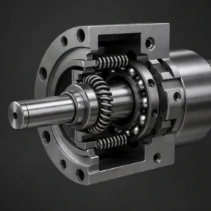
Constant-pressure preload uses a custom wave spring or another compliant mechanism to maintain a relatively stable axial force as the assembly expands or contracts.
It can reduce preload fluctuations caused by temperature changes, although its stiffness characteristics differ from those of a rigid position-preloaded arrangement.
| Method | How It Works | Advantage | Limitation |
|---|---|---|---|
| Position Preload | Fixed axial displacement | High positioning rigidity | Sensitive to differential thermal expansion |
| Constant-Pressure Preload | Spring maintains axial force | Accommodates thermal movement | Requires careful spring force and stiffness design |
Speed and Thermal Management: Understanding DN Values
DN value helps engineers compare bearing speed conditions, but it should not be used as a standalone permissible speed rating.
It is calculated by multiplying the bearing bore diameter by rotational speed:
DN = d × n
- d: Bearing bore diameter in millimeters (mm).
- n: Rotational speed in revolutions per minute (RPM).
For example, a spindle bearing with a 50 mm bore operating at 20,000 RPM has a DN value of:
50 × 20,000 = 1,000,000 mm·RPM
Two bearings can have the same DN value but different permissible speeds. Internal geometry, cage design, preload, lubrication, and cooling all influence actual performance.
Use the manufacturer’s speed data for the specific bearing and operating configuration rather than relying on a universal DN limit.
Grease, Oil-Air, and Oil-Jet Lubrication
Lubrication affects both bearing life and spindle temperature. The choice depends on speed, load, operating hours, and the amount of heat that must be removed.
Grease lubrication is common in compact precision spindles. It requires relatively little equipment and can provide long service intervals when the correct grease quantity and specification are used.
However, excessive grease can increase churning losses. At high speeds, the lubricant may generate more heat than the bearing can dissipate. Grease also has a finite service life and must be selected for the actual operating conditions.
Oil-air lubrication supplies a small, controlled quantity of oil with compressed air. It is widely used in high-speed CNC spindles because it delivers lubricant without filling the bearing cavity with excess oil.
The system needs accurate metering, reliable compressed air, and correctly designed delivery lines. An interrupted oil supply can quickly damage a high-speed bearing.
Oil-jet lubrication directs a controlled oil flow into the bearing. It can provide both lubrication and cooling in demanding spindle applications.
Oil-jet systems require pumps, filtration, temperature control, and oil recovery. The jet position and flow rate must be designed to avoid excessive churning.
| Lubrication Method | Advantages | Limitations | Typical Application |
|---|---|---|---|
| Grease | Simple system and low maintenance | Finite lubricant life and limited heat removal | General-purpose precision spindles |
| Oil-Air | Controlled oil delivery with limited excess lubrication | Requires accurate metering and compressed air | High-speed CNC spindles |
| Oil-Jet | Lubrication and effective heat removal | More complex circulation and cooling equipment | Demanding high-speed spindle systems |
How Hybrid Ceramic Bearings Extend Speed Capability
Hybrid ceramic bearings can improve high-speed performance by reducing rolling element mass. Their silicon nitride balls generate lower centrifugal forces than comparable steel balls at the same speed.
This helps control internal dynamic loading and can reduce friction-related heat.
However, changing from steel balls to ceramic balls does not automatically increase the permissible speed of an existing spindle. Cage design, raceway geometry, preload, lubrication, and cooling must all support the intended operating speed.
Precision Classes: ABEC 7 vs. ABEC 9 and ISO P4 vs. UP
Higher bearing precision can reduce rotational errors, but the highest available grade is not always necessary. The correct choice depends on the spindle’s runout requirements, operating speed, machining tolerance, and overall assembly accuracy.
Before comparing grades, it is important to understand that ABEC and ISO use different classification systems.
Understanding ABEC and ISO Precision Classes
ABEC is a precision classification system defined by the Annular Bearing Engineers’ Committee under ABMA. ISO 492 specifies dimensional and running accuracy tolerances for rolling bearings.
ABEC 7 and ABEC 9 represent increasingly restrictive precision requirements. Under the ISO system, P4 and P2 are commonly used precision grades, with P2 representing a higher precision level than P4.
UP is a super-precision designation used by some bearing manufacturers. Its exact requirements must be checked against the manufacturer’s documentation rather than assumed to be a universal ISO or ABEC equivalent.
| Classification | General Precision Level | Typical Application |
|---|---|---|
| ABEC 7 | High precision | Precision machinery and spindle applications |
| ABEC 9 | Very high precision | Applications requiring tighter tolerances |
| ISO P4 | High precision | Precision machine tool spindles |
| ISO P2 | Higher precision than P4 | Very demanding precision applications |
| UP | Manufacturer-specific super-precision designation | High-end spindle applications |
Do not assume that ABEC 7 is directly equivalent to P4 or that ABEC 9 is identical to UP. Compare the actual tolerance requirements and manufacturer specifications before purchasing.
How Precision Grade Affects Spindle Runout and Surface Finish
Higher bearing precision can reduce bearing-related runout and rotational variation. This matters when a grinding spindle must maintain consistent wheel positioning or when a machining center produces components with tight dimensional tolerances.
But bearing accuracy is only one part of the system.
Tool balance, spindle geometry, housing accuracy, vibration, thermal growth, and cutting conditions also affect the finished surface. A P2 bearing cannot compensate for an inaccurately machined housing or a poorly balanced tool assembly.
Choosing the Right Precision Grade
Use the spindle’s actual performance requirements to determine the grade:
- General CNC machining: Select a precision class that meets the machine manufacturer’s runout and positioning requirements.
- High-speed machining: Prioritize a verified speed rating, suitable cage, matched bearing set, and controlled lubrication.
- Precision grinding: Consider P4 or higher precision designs, including manufacturer-specific super-precision options where required.
For procurement teams, comparing actual runout tolerances, preload specifications, speed limits, and service conditions is more useful than choosing a bearing based on its grade label alone.
4. Application Guide: Matching Spindle Bearings to Your Machining Needs
The bearing arrangement should follow the machining process, not the other way around. High-speed milling prioritizes rotational speed and heat control. Heavy-duty turning needs radial stiffness. Precision grinding demands consistent runout and thermal stability.
The following configurations provide practical starting points. Final specifications should be verified against cutting forces, spindle geometry, and bearing manufacturer data.
High-Speed Milling and Drilling
For high-speed milling and drilling, prioritize low friction, controlled temperature, and stable rotation. A bearing arrangement that generates excessive heat can cause spindle growth and change tool positioning during a long machining cycle.
Typical configuration:
- Angular contact ball bearings for combined radial and axial support.
- Hybrid ceramic balls to reduce rolling element centrifugal forces.
- Light preload where sufficient for the required rigidity.
- Oil-air lubrication for controlled lubricant delivery.
- Effective spindle cooling and temperature monitoring.
Consider an aluminum machining center operating at 20,000–30,000 RPM. The spindle may spend long periods at high speed, with frequent acceleration and deceleration. In this situation, controlling friction and thermal growth is essential.
The final selection must also account for tool weight, cutting forces, acceleration rates, and the spindle manufacturer’s maximum speed rating.
Heavy-Duty Turning and Boring
Heavy-duty turning and boring generate substantial radial cutting forces. The spindle must resist shaft displacement while maintaining tool-to-workpiece alignment.
Typical configuration:
- Cylindrical roller bearings for high radial load capacity and stiffness.
- Angular contact ball bearings for axial support and spindle positioning.
- Medium or higher preload when justified by the load and speed conditions.
- Lubrication and cooling designed for sustained operating loads.
- Appropriate bearing spacing to control shaft deflection and moment loading.
For example, a large boring machine cutting a steel housing may experience heavy radial forces and relatively low spindle speeds. A cylindrical roller bearing arrangement can support these forces, while angular contact bearings provide the required axial positioning.
Heavy preload should not be applied automatically. If the spindle also operates at high speed, excessive preload can increase temperature and reduce bearing life.
Precision Grinding and High-Finish Machining
Precision grinding places strict demands on spindle runout, vibration, and thermal stability. Small changes in wheel position can affect grinding depth, surface texture, and final dimensions.
Typical configuration:
- Super-precision angular contact ball bearings.
- ISO P4 or higher precision grades where required.
- Matched bearing sets with controlled preload.
- Thermal management to limit spindle growth.
- Strict control of cleanliness, balance, and installation accuracy.
For a grinding spindle, simply installing a higher-grade bearing is not enough. The housing, shaft, grinding wheel, and cooling system must all maintain the required accuracy.
Temperature monitoring is particularly useful during commissioning. A spindle that runs accurately when cold may develop measurable axial growth after reaching its operating temperature.
| Application | Preferred Bearing Arrangement | Preload Strategy | Main Priority |
|---|---|---|---|
| High-Speed Milling | Hybrid ceramic angular contact bearings | Light, application-dependent | Speed and thermal stability |
| Heavy-Duty Turning | Cylindrical roller and angular contact bearings | Medium to higher, as required | Radial rigidity and load capacity |
| Precision Grinding | Super-precision angular contact bearings | Precisely controlled | Runout and thermal stability |
5. Installation, Rebuilds, and Common Spindle Bearing Failure Modes
Most premature spindle bearing failures are linked to lubrication problems, contamination, incorrect mounting, excessive preload, or electrical damage. Replacing the bearing without identifying the cause often leads to another failure.
A spindle rebuild should therefore include inspection of the shaft, housing, spacers, lubrication passages, and mounting surfaces, not just the rolling bearings.
Spindle Rebuild Checklist: From Disassembly to Installation
Precision spindle bearings require controlled handling throughout the rebuild. A small installation error can damage the raceways or change the intended preload before the spindle returns to service.
1. Record the Original Bearing Arrangement
Before disassembly, document the bearing orientation, matched set arrangement, spacer positions, preload mechanism, and axial locating configuration.
Take photographs and label components where necessary. This is particularly important for angular contact bearings because installing a bearing in the wrong orientation can change the direction of axial load support.
Use the spindle manufacturer’s disassembly procedure and appropriate extraction tools. Never transmit hammering forces through the rolling elements.
2. Clean and Inspect the Shaft and Housing
Clean the spindle shaft, housing bores, shoulders, spacers, and lubrication passages using approved materials.
Check for:
- Wear, scoring, and corrosion on shaft journals.
- Fretting or dimensional damage in housing bores.
- Damaged or uneven shoulder surfaces.
- Spacer thickness and parallelism errors.
- Blocked lubrication passages and contaminated seals.
Measure critical mounting dimensions before installing new bearings. A replacement bearing cannot correct a worn shaft journal or an oversized housing bore.
3. Verify Shaft and Housing Fits
The fit between a bearing ring and its supporting component determines whether the ring stays in position or moves during operation.
An interference fit is commonly used when a bearing ring must resist creep relative to its mounting surface. For example, the inner ring of a rotating spindle bearing often requires a controlled interference fit on the shaft.
A clearance or more lightly constrained fit may be appropriate where a bearing ring needs to accommodate axial movement or thermal expansion. This is common in floating bearing arrangements.
Do not apply one universal fit recommendation to every spindle. The correct shaft and housing tolerances depend on bearing size, load direction, operating temperature, and the manufacturer’s mounting specifications.
4. Heat Bearings Correctly Before Installation
When an interference fit is required, controlled heating expands the bearing ring and makes installation easier.
Use an induction heater or another approved temperature-controlled method. Measure the bearing temperature directly.
For many conventional steel bearings, installation temperatures around 80–100°C are commonly used, but this is not a universal limit. The manufacturer’s instructions take priority, particularly for bearings with special cages, seals, coatings, or dimensional stabilization requirements.
Avoid open flames and uncontrolled heating. Excessive temperature can damage bearing components or affect dimensional stability.
After installation, allow the bearing to cool under controlled conditions and verify that it has seated correctly against the shaft or housing shoulder.
5. Set Preload and Check Spindle Accuracy
Once the bearings are installed, verify their orientation, spacer dimensions, axial positioning, and preload.
Incorrect spacer thickness can create excessive preload or unwanted internal clearance. Both conditions affect spindle performance. If your facility lacks the capability to manufacture custom precision spacers or complex machined components, consider outsourcing to maintain exact tolerances.
Before returning the spindle to production, check:
- Radial and axial runout.
- Spindle rotation and mechanical smoothness.
- Preload or axial displacement, where specified.
- Lubrication supply and delivery pressure.
- Vibration and temperature during controlled run-in.
Why Spindle Bearings Fail: Four Common Causes
When a spindle bearing fails, the damage pattern often provides clues about the underlying problem. Heat, raceway indentations, electrical craters, and abnormal vibration point toward different failure mechanisms.
Identifying these symptoms before replacing the bearing helps prevent repeat failures. Similar to tracking failure modes in precision flat springs, diagnosing the root cause is crucial.
1. Lubricant Degradation and Grease Dry-Out
Lubricant degradation increases friction and reduces the protection between rolling elements and raceways.
In grease-lubricated spindle bearings, the base oil may gradually become depleted in the contact zone. High temperature, oxidation, contamination, and excessive mechanical stress can accelerate lubricant deterioration.
Common warning signs include:
- Rising bearing operating temperature.
- Abnormal noise or vibration.
- Discolored or contaminated grease.
- Visible raceway wear.
Prevention: Use the specified lubricant, control grease quantity, follow appropriate maintenance intervals, and monitor operating temperature. For high-speed applications, consider oil-air lubrication where the spindle design supports it.
2. Foreign Particle Contamination
Metal chips, dust, abrasive particles, and moisture can enter a bearing through damaged seals, contaminated lubricant, or poor installation practices.
Hard particles trapped between rolling elements and raceways create indentations. As the bearing rotates, these damaged areas produce repeated contact stresses, which can accelerate surface fatigue.
Prevention:
- Maintain a clean bearing assembly environment.
- Inspect seals and sealing surfaces during rebuilds.
- Use suitable lubricant filtration.
- Keep exposed bearings covered during installation.
- Prevent contaminated tools and cleaning materials from contacting precision surfaces.
3. Electrical Pitting and Electrical Erosion
Electrical damage occurs when current passes through the rolling contacts between bearing elements and raceways.
In motor-driven spindles, electrical potential can develop between the shaft and housing. Variable-frequency drives may contribute through common-mode voltage and high-frequency bearing currents when grounding and insulation are inadequate.
Electrical discharge creates small craters on the raceways, known as electrical pitting. Continued operation can produce a fluted or washboard-like surface pattern.
Typical symptoms include:
- High-frequency bearing noise.
- Increasing vibration.
- Small craters or discoloration on raceways.
- Regular fluting patterns caused by progressive electrical erosion.
Prevention:
- Check motor and spindle grounding.
- Use shaft grounding rings where appropriate.
- Consider insulated bearing arrangements when required by the electrical design.
- Use hybrid ceramic bearings to electrically isolate the rolling contacts.
- Address inverter-related currents through suitable grounding, cabling, and filtering.
Hybrid ceramic bearings reduce current passage through the rolling contacts, but they do not eliminate every possible electrical path. The spindle and drive system still need appropriate electrical protection.
4. Incorrect Preload and Installation Damage
Excessive preload increases internal contact forces and frictional heat. Insufficient preload can allow unwanted movement and unstable rolling contact.
Installation damage can create problems before the spindle even starts running. Hammering a bearing into position, applying force through the wrong ring, or using inaccurate spacers can damage raceways and alter internal clearance. Using properly manufactured precision stamped components and shims helps avoid these tolerance stack-up issues.
Prevention: Follow the bearing manufacturer’s mounting procedure, verify shaft and housing fits, measure spacer dimensions, and use suitable installation equipment. During commissioning, monitor runout, vibration, and temperature.
| Failure Mode | Typical Symptoms | Preventive Action |
|---|---|---|
| Lubricant degradation | Heat, noise, friction, raceway wear | Correct lubricant selection and maintenance |
| Contamination | Raceway indentations and abnormal vibration | Clean installation and effective sealing |
| Electrical pitting | Cratering, fluting, high-frequency vibration | Grounding, insulation, or hybrid ceramic bearings |
| Incorrect preload | Excessive heat or unstable spindle movement | Controlled preload and accurate assembly |
6. FAQs About Machine Tool Spindle Bearings
The following answers address three common questions from CNC spindle maintenance engineers, machine tool buyers, and technicians planning a spindle rebuild.
Can I Use Standard Bearings in a CNC Spindle Rebuild?
Not as a direct replacement unless the bearing has been verified against the spindle’s engineering requirements.
A standard commercial bearing may have the correct bore and outside diameter but still differ in precision class, internal clearance, cage design, preload characteristics, and permissible speed.
For a CNC spindle rebuild, use the original bearing specification or an approved engineering alternative. Dimensional compatibility alone is not enough.
What Is the Best Bearing Material for High-Speed Spindles?
Hybrid ceramic bearings with silicon nitride balls are often a strong choice for high-speed precision spindles.
Their lower rolling element mass reduces centrifugal forces at high RPM. Silicon nitride also offers high hardness, wear resistance, and electrical insulation.
However, all-steel precision bearings can still be suitable for many spindle applications. The decision should consider operating speed, load, preload, lubrication, temperature, and the complete bearing design. You can also review our material selection guide for other high-performance metal options.
How Often Should Spindle Bearings Be Replaced?
There is no fixed replacement interval for all machine tool spindle bearings. Service life depends on operating hours, rotational speed, cutting loads, lubrication, contamination, temperature, and installation quality.
Some spindles operate reliably for years. Others require rebuilding much earlier because of lubrication problems, electrical damage, or excessive operating temperatures.
Monitor these indicators instead of relying only on calendar-based replacement:
- Temperature: A consistent increase may indicate friction, preload problems, or lubricant deterioration.
- Vibration: Changes in vibration can reveal raceway damage, imbalance, or bearing wear.
- Runout: Increasing radial or axial runout may indicate bearing deterioration or mounting problems.
- Lubrication: Check lubricant condition, delivery pressure, and supply consistency.
- Machining quality: New surface defects or dimensional variation may indicate changes in spindle condition.
When these indicators change, investigate the cause before deciding whether bearing replacement or a complete spindle rebuild is necessary.
Conclusion: Select Spindle Bearings for the Actual Operating Conditions
The right machine tool spindle bearing depends on the forces, speed, accuracy, and temperature conditions the spindle must handle.
- Choose angular contact ball bearings when combined radial and axial support is required.
- Use cylindrical roller bearings when radial load capacity and stiffness are the main priorities.
- Consider hybrid ceramic bearings for high-speed applications where rolling element mass and heat generation matter.
- Use thrust bearings when the spindle design requires dedicated axial load support.
Then verify the details that determine actual performance: contact angle, preload, DN value, lubrication method, precision grade, and mounting fits.
For a spindle rebuild, inspect the shaft and housing before installing replacement bearings. Check the original arrangement, confirm the preload, and monitor temperature and vibration during commissioning.
A bearing that matches the spindle’s actual operating conditions is more likely to maintain machining accuracy, avoid premature failure, and keep production running without unnecessary downtime. For highly specialized applications requiring custom precision springs or bespoke mechanical solutions, consult with our engineering team.