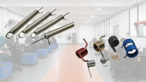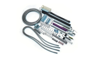
Torsion and extension springs solve the same counterbalance problem through different force mechanisms, and that difference propagates through the entire value chain — component count, tolerance requirements, SKU structure, installation procedure, warranty exposure, and aftermarket service model.
This guide is written for procurement teams, design engineers, and distributors who need to compare the two systems at the product and supply level rather than at the homeowner decision level. It covers operating principles, a side-by-side mechanical comparison, manufacturing and sourcing cost structure, failure modes and compliance considerations, channel and installation requirements, and a selection checklist for B2B evaluation.
Definition, Boundaries, and Applications
A torsion spring stores energy by twisting around an axis. In a garage door system it is mounted horizontally above the door on a shaft. As the door closes, the spring winds and stores energy; as the door opens, that energy is released through the shaft and cable drums to counterbalance the door’s weight.
An extension spring stores energy by stretching. Garage door extension springs are positioned along the horizontal tracks on either side of the door. They extend as the door closes and contract as the door opens, using tension to assist movement. Both types reduce the force required to move a heavy door, but their mechanisms, mounting locations, supporting hardware, and service requirements differ — and those differences are what drive the engineering and sourcing trade-offs.
The comparison has a practical boundary. A spring suitable for a residential garage door may not be suitable for an industrial machine, hinge, lever, lift, robotic arm, exercise device, trampoline, or wind-up mechanism. Selection depends on required movement, available envelope, load, travel distance, spring rate, and connection geometry. A spring should be specified as part of a complete mechanism, never by appearance or unit price alone.
Key Specification Quick Reference
Before the detailed comparison, the table below consolidates the parameters that determine spring compatibility. For procurement and engineering, these are the numbers that should appear on a supplier datasheet or RFQ response.
| Parameter | Typical range / values | How to verify |
|---|---|---|
| Wire diameter (torsion, residential) | Most residential springs run between .207″ and .250″; the full residential range is commonly cited as .192″–.273″ | Measure the length of 10 or 20 compressed coils and divide by coil count; a caliper on a single coil can be skewed by paint and corrosion by up to .010″ |
| Inside diameter (ID) | 1-3/4″ (most common residential); 2″ (heavier residential and light commercial); larger IDs for commercial shaft sizes | Stamped on the winding cone or stationary cone (e.g., “175” or “P175” for 1-3/4″); can also be measured across the coil opening |
| Wind direction | Left-wound and right-wound are not interchangeable; cone color commonly encodes direction (red for right-wound, black for left-wound on many brands) | View the spring end: coils angling up to the right as they recede are right-wound; DASMA 103 requires wind direction in the spring marking |
| IPPT (inch-pounds per turn) | Derived from wire size, ID, and active coil count; a .250″ wire spring is roughly 1.7× stronger than a .225″ spring of the same diameter and length | IPPT = (28,500,000 × d⁴) ÷ (10.8 × D × N), where d = wire diameter, D = inside diameter, N = active coil count; supplier should provide IPPT or the inputs to calculate it |
| Cycle rating | 10,000 cycles is the ANSI/DASMA 103 baseline for standard residential; 25,000 and 50,000 cycles are common commercial tiers | Cannot be measured from a spring; it is a spec printed on the invoice, spring tag, or test report |
| DASMA color code | Wire gauge is indicated by a paint stripe on the coil body (e.g., .207 = yellow, .218 = white, .225 = red, .243 = green, .250 = gold, .262 = blue, .273 = orange) | Color is a starting point only; DASMA guidance states color codes must be verified by direct measurement |
Wire diameter ranges and ID values above are reference points for screening, not acceptance criteria. The supplier’s datasheet and the actual door weight calculation govern the specification. IPPT is a derived property, not a catalog dimension — two springs with the same wire and ID but different active coil counts will have different IPPT.
Types, Categories, and Operating Principles
The most useful engineering classification is based on how the spring stores and releases energy. A torsion spring is a rotational spring: its working action is measured in torque and angular deflection. An extension spring is a tension spring: its working action is measured in pulling force and linear extension. This distinction explains why the two systems use different mounting locations, different supporting hardware, and different installation procedures even when they perform the same broad function.
For a garage door, the operating sequence is straightforward to model. With a torsion system, closing the door winds the spring and loads the shaft; opening the door allows the spring to unwind and transfer force through the drums and cables. With an extension system, closing the door stretches the springs along the tracks; opening the door allows them to contract and pull through the cable and pulley arrangement. If cables are misrouted, pulleys are worn, or the spring is incorrectly sized, the intended balance will not be achieved — and the failure will show up as door imbalance, opener overload, or premature component wear.
When specifying a spring for a mechanical application, classify the movement before selecting a catalog dimension. Determine whether the mechanism needs rotary torque or linear tension, how far it must move, how much load it must carry, how often it will cycle, and how much space is available. Free length, wire diameter, coil diameter, active coil count, attachment style, and spring rate all influence behavior. Two springs that look similar may not be interchangeable.
Torsion Springs
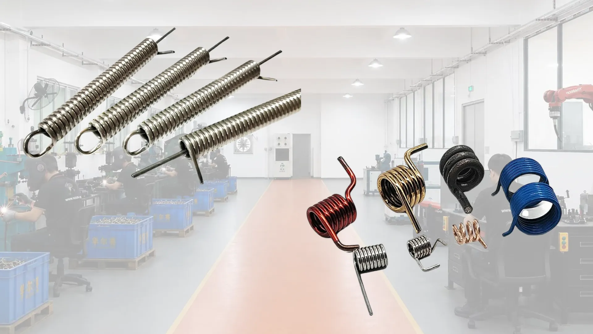
A torsion spring is a helical coil designed to resist twisting. Its ends are formed into legs or other attachment features that connect to a stationary point and a moving component. In a garage door, the spring works with a shaft and cable drums: the shaft transfers rotational force while the drums guide the cables that lift the door from both sides.
This arrangement distributes the door’s load more evenly and provides controlled movement through the opening cycle. It also keeps the main spring assembly in a defined position above the door. The result can be quieter and smoother operation when the spring, cables, drums, shaft, and door are correctly matched. The same precision that produces this result is also the constraint: incorrect winding, wrong dimensions, poor alignment, or damaged hardware can compromise the entire balance.
Torsion springs are not limited to garage doors. They are used in hinges, levers, lifting equipment, industrial machinery, robotic systems, and automated mechanisms that require a return force or controlled rotational movement. Design must account for working angle, torque, cycle requirements, mounting geometry, and wind direction. A torsion spring should be specified for the mechanism’s actual operating conditions rather than selected by outer diameter or length alone.
Extension Springs
An extension spring is a helical coil that stores energy as it is pulled beyond its free length. Its ends commonly include hooks, loops, or other formed attachments. In a garage door, extension springs are installed along the tracks and connected to cables and pulleys so that the spring’s contraction helps counterbalance the door.
The design is useful where a linear pulling force is required and where the mechanism provides sufficient travel for the spring to extend and contract. Extension springs appear in garage door systems and in other equipment that uses tension to return, assist, or counterbalance a moving part. Effectiveness depends on preload, extension distance, spring rate, attachment security, and alignment of surrounding components.
Because extension systems typically include several moving or connected parts, the bill of materials extends beyond the coil itself. Cables, pulleys, anchors, and safety cables should be specified and inspected as part of the system. A spring that appears intact may still be unsuitable if it has lost tension, has been stretched beyond its intended range, or is paired with the wrong door load. The spring and its support system must be evaluated together.
Mechanical Comparison at a Glance
| Criterion | Torsion system | Extension system |
|---|---|---|
| Force mechanism | Rotational torque via shaft and cable drums | Linear tension via cable and pulley arrangement |
| Mounting location | Above the door on a horizontal shaft | Alongside the horizontal tracks |
| Force distribution | More even across both sides through a common shaft | Side-by-side; requires matched spring pairs and careful alignment |
| Cycle life basis | Standard residential grade commonly rated at 10,000 cycles under ANSI/DASMA 103-2017; high-cycle tiers at 25,000 / 50,000 cycles are available and specified by program | Standard residential grade commonly rated at 10,000 cycles; high-cycle tiers are limited by coil geometry and door design, and should be confirmed against the supplier’s test data |
| Component count per door set | Lower — one or two springs plus shaft, drums, bearing plates | Higher — two or more springs plus cables, pulleys, safety cables |
| SKU and variant complexity | Higher — left-hand and right-hand variants, multiple wire sizes and cycle tiers | Lower — more standardized lengths and rates; fewer handed variants |
| Installation procedure | Winding and balancing required; higher installer skill floor | Bolt-on along tracks; more components to secure |
| Containment on failure | Spring generally stays on the shaft; winding components remain a hazard under load | Safety cables are critical — a broken spring can travel if not restrained |
Cycle ratings are minimum acceptance values, not marketing ranges. ANSI/DASMA 103-2017 sets 10,000 cycles as the baseline for standard residential counterbalance springs, with high-cycle grades at 30,000 cycles or higher available for high-use situations. For commercial and industrial programs, project specifications commonly require 25,000, 50,000, or 100,000 cycles and should be verified against the test method in ANSI/DASMA 109-2017 rather than accepted as a catalog label. Wire diameter scales with cycle rating — typical 10,000-cycle torsion springs use 0.225″–0.243″ wire, 25,000-cycle use ~0.250″, and 50,000-cycle use ~0.263″ — so the rating is a physical fatigue property, not a software flag.
Selection matrix: door weight, cycle demand, and headroom
The table maps typical program parameters to a starting recommendation. It is not a substitute for the supplier’s calculation, but it gives procurement and engineering a defensible first position before RFQ.
| Program condition | Starting recommendation | Basis | Specification starting point (verify with supplier) |
|---|---|---|---|
| ≤300 lb door, existing horizontal-track platform, cost-dominant | Extension system | Component cost and SKU simplicity outweigh cycle life in low-frequency residential use | Extension spring rated to door weight; specify safety cable as system component; confirm hook/loop end configuration and matched pair |
| 400–600 lb door, ≥6 cycles/day, target ≥15,000 cycles | Torsion system, standard grade | Even force distribution through shaft and drums; torsion commonly specified for heavier doors with consistent balance requirements | Typical starting range: .225″–.250″ wire, 1-3/4″ or 2″ ID, oil-tempered per ASTM A229; confirm IPPT and active coil count against door weight and drum radius |
| >600 lb door, or ≥25 cycles/day, or target ≥50,000 cycles | Torsion system, high-cycle grade, with documented test data per ANSI/DASMA 109 | Project specifications for commercial and high-use doors commonly require 25,000–100,000 cycles; verify wire diameter and test protocol before accepting the rating | Higher wire diameter relative to 10k-cycle baseline (e.g., .250″ for ~25k, .263″ for ~50k in common residential/commercial sizes); confirm ID and coil count for the target IPPT; require test report, not catalog label |
| Limited headroom below standard 12″ | Low-headroom torsion configuration (front-mount or double-track) | Low-headroom torsion can reduce required clearance to 9.5″ or as low as 4.5″ in some rear-mount configurations; confirm with the specific door and track supplier | Confirm wire/ID/coil count are compatible with the reduced-radius drum; low-headroom geometry changes the IPPT-to-door-weight relationship and must be calculated, not copied from a standard-headroom spring |
| Existing extension platform, no structural change permitted | Extension system, matched set with safety cables specified as system components | Conversion to torsion is a redesign requiring shaft, drums, cable, track, and mounting-point changes — not a spring swap | Measure both existing springs independently — roughly 30% of multi-spring doors use mismatched wire sizes; specify safety cable diameter and attachment points per system design |
Headroom and backroom dimensions vary by door height, track radius, and opener configuration. The values above are starting thresholds for screening, not installation drawings. Final clearance should be confirmed against the door manufacturer’s published headroom requirement and the specific track profile.
Advantages and Limitations by System
Torsion Springs: Strengths and Constraints
Torsion springs provide smoother and more even assistance because torque is transmitted through a shaft and cable drums. The spring assembly is organized above the door, which can reduce exposed movement near the tracks. Torsion designs are also commonly associated with longer service life, often described in the 15,000–20,000 cycle range. These characteristics make them attractive for heavier doors, high-frequency operation, and applications where consistent balance is a product requirement.
The constraints are equally relevant at the product level. Torsion systems require tighter tolerances on leg geometry, wind direction (left-hand vs right-hand), and torque rate, which increases manufacturing complexity and SKU count. Installation requires accurate winding and adjustment, which raises the installer skill floor and makes channel training part of the product support burden. A torsion system is not maintenance-free, and a worn cable, bearing, drum, or mounting point can still compromise operation. Torsion is appropriate when the door structure and available headroom support the system — not simply because it is often positioned as the premium option.
Extension Springs: Strengths and Constraints
Extension springs offer a compact side-mounted arrangement and are a practical fit for doors already designed around horizontal tracks, cables, and pulleys. Because they work through stretching and contraction, they provide useful force over a longer movement path where the surrounding mechanism is designed for that action. From a manufacturing standpoint, extension springs are generally simpler to form (hook or loop ends) and more forgiving on rate tolerance, which can translate into lower per-unit cost and a simpler SKU structure.
The constraints include greater dependence on supporting hardware, more exposure to alignment and pulley wear, and a commonly shorter cycle life than torsion systems. Extension systems also depend on effective safety cables, and that dependency becomes a product-design responsibility: the safety cable and its attachment points must be specified as part of the system, not as an aftermarket accessory. Extension springs are suitable when space, existing design, and target cost support them and when the full safety system is engineered and installed correctly.
Cost Structure from a Manufacturing Perspective
For a manufacturer, the cost comparison between torsion and extension springs is not a question of which system is cheaper to install — it is a question of where cost concentrates across the bill of materials, the production process, inventory, and warranty exposure. The table below compares the two systems on those dimensions.
The table is a structural comparison, not a price list. Actual figures depend on wire diameter, coil count, material grade, coating, target cycle rating, order volume, and the specific door weight the system is designed for.
| Cost driver | Torsion system | Extension system |
|---|---|---|
| Component count per door set | Lower — one or two springs plus shaft, drums, and bearing plates | Higher — two or more springs plus cables, pulleys, and safety cables |
| Manufacturing complexity | Higher — tighter tolerance on leg geometry, wind direction, and torque rate | Lower — simpler hook or loop ends and more forgiving rate tolerance |
| SKU and inventory burden | Higher — left-hand and right-hand variants, multiple wire sizes, cycle-rating tiers | Lower — more standardized lengths and rates; fewer handed variants |
| Material and coating cost | Generally higher per unit for equivalent torque — larger wire diameter and heavier coil mass | Generally lower per unit — smaller wire, lighter coil |
| Warranty and claim exposure | Lower cycle-claim rate when specified correctly; failures are contained on the shaft | Higher claim exposure — fatigue, hook deformation, and safety-cable dependency |
| Installation and channel support | Higher — winding, balancing, and precise alignment require installer training | Lower — bolt-on along tracks, though more components to secure |
In summary: the torsion system concentrates cost in tighter tolerances, handed variants, and heavier wire, while the extension system spreads cost across more components and higher warranty exposure. The sourcing decision is not “which is cheaper to make” in the abstract, but which cost structure fits the target door weight, target cycle rating, distribution channel, and aftermarket service model. For a closer look at how those tolerances are held in production, see Hessp’s manufacturing capabilities.
Failure Modes, Safety, and Design Considerations
The primary engineering risk in both systems is stored energy. Both can release force suddenly if they break, are incorrectly adjusted, or are removed without controlling the load. A torsion spring releases rotational energy through the shaft and winding components. An extension spring can extend or detach suddenly, and a broken spring may travel away from its mounting point if not restrained. Safety cables are therefore a system-level requirement for extension designs, not an accessory — they should be specified, validated, and documented as part of the assembly.
For extension designs, safety cables should be specified with a documented safety factor and attachment validation. Project specifications for commercial doors commonly require cable safety factors of 5:1 to 8:1, and cable diameter should be checked against the drum or sheave diameter — DASMA guidance limits cable diameter to no more than 5% of the drum or sheave it runs on. The safety cable is a system component with its own load path, not a generic accessory.
The practical distinction matters at the design stage: a torsion spring that releases under load can send a winding bar through nearby surfaces; an extension spring that detaches without a safety cable can travel across the installation envelope. The hazard is not the spring at rest — it is stored energy being released without a controlled path. That reality should drive the design of installation instructions, warning labels, and any included or recommended safety hardware.
Spring specification is the other principal risk vector. A spring that is too weak leaves the opener carrying excessive load; a spring that is too strong can make the door difficult to control or prevent correct closing. Incorrect installation leads to premature wear and can damage the opener or adjacent door components. Spring selection must therefore be based on the door’s actual weight, dimensions, travel, hardware, and required balance — not on a visual match or a “close enough” rate. For OEM and aftermarket programs, this is also a documentation requirement: the specification that produced the correct balance should be traceable and repeatable.
A broken spring is not the only failure signal. A door that rises unevenly, becomes unusually heavy, makes new sounds, fails to stay in position, or vibrates excessively may have a spring, cable, pulley, track, or balance problem. These symptoms are relevant to distributors and installers as diagnostic indicators, and to manufacturers as field-failure patterns that should feed back into design and quality review.
Commercial compliance: OSHA and building code touchpoints
For commercial and industrial door programs, ANSI/DASMA standards are the design baseline, but project specifications and facility compliance often bring additional requirements that should be captured in the RFQ and the product documentation.
Entrapment protection. Motorized commercial doors must include safety devices that stop or reverse the door when an obstruction is detected — commonly photo-eye sensors, safety edges along the bottom of the door, and auto-reverse systems. These components must remain aligned and functional; a damaged or disconnected sensor is a recognizable hazard under OSHA’s general duty clause, even where no door-specific standard is cited.
Door balance and free-fall protection. Commercial doors must remain properly balanced so lift systems and openers operate correctly. OSHA has cited employers for failing to control stored energy in counterbalance systems during maintenance and repair, and one acceptable abatement method is to unwind the torsion springs to remove potential energy before work begins. For door design, this translates into specifying supplemental safety devices where the project or facility requires them — door stops, safety arms, cable tension systems, or controlled descent mechanisms that prevent sudden free-fall if a component fails.
Cargo door counterweights. For facilities covered by OSHA’s marine terminals standard (29 CFR 1917.114), cargo door counterweights must be guarded, and lifting bridles and tackles must have a safety factor of five based on maximum anticipated static loading. This is a narrow but concrete example of how OSHA requirements can drive hardware selection beyond the ANSI/DASMA baseline.
Building code and redundancy. Commercial installations are more broadly subject to inspection under adopted building codes, including the International Building Code (IBC) as adopted at the state or local level. Critical openings may require redundant lift components or shaft-mounted brakes as a project specification, even where the product standard does not mandate them. These requirements should be confirmed with the authority having jurisdiction (AHJ) and written into the RFQ as explicit line items, not left to the supplier’s standard configuration.
Installation Requirements and Channel Considerations
Torsion and extension systems require different installation conditions, and those differences have direct channel implications. A torsion system needs suitable space above the door for the spring, shaft, drums, and mounting hardware, and requires accurate alignment so the shaft and cables distribute force correctly. An extension system needs usable space along the horizontal tracks and a compatible arrangement of cables, pulleys, anchor points, and safety cables. Limited headroom may influence system choice, but available space must be assessed as part of the entire door assembly rather than in isolation.
For distributors and installers, the two systems imply different training, tooling, and service economics. Torsion work requires winding bars, balance measurement, and a skill level that must be trained and verified. Extension work requires careful alignment and safety-cable verification but generally uses simpler tooling. A manufacturer supporting both systems should expect different warranty claim patterns, different technical-support call profiles, and different spare-parts inventory structures for each.
Before a replacement or new build is specified, collect the information that determines spring compatibility: spring type, door width and height, door material, approximate door weight, track configuration, number of springs, shaft or cable arrangement, and existing spring dimensions. For custom mechanical applications, also capture required load, travel distance, operating angle, cycle frequency, available envelope, attachment style, and desired spring rate. A replacement should restore a balanced system rather than simply insert a new coil into an aging assembly.
Comparing the Options and Making the Trade-Off
The clearest way to compare the two systems is to evaluate the same criteria for both: force mechanism, installation location, envelope requirements, load distribution, cycle life, containment on failure, maintenance profile, component cost, and replacement complexity. Torsion springs generally offer more controlled rotational counterbalance and can use less overall space above the door when the installation is compatible. Extension springs can be simpler and lower-cost in some existing designs, but they rely on more supporting components and require careful restraint and alignment.
For a heavy, insulated, or high-frequency door, controlled force distribution and durability may carry more weight than the lowest component price. For an existing design with restricted headroom or an established extension arrangement, a properly matched extension system may remain the practical choice. Conversion from one type to another is not a spring swap: it can require changes to the shaft, drums, cables, tracks, mounting points, and door balance, and it should be treated as a redesign rather than a part substitution.
The word “better” therefore depends on the operating requirement. If the priority is smoother operation, compact organization, and longer cycle life, torsion is often the stronger candidate when the door can support it. If the priority is matching an existing platform, working within limited space, or controlling component cost, extension may be appropriate. The final decision should be confirmed by system compatibility, test data, and a documented specification.
Supply Model: Stock Standard vs Custom OEM
The sourcing decision is not only which spring system to specify, but which supply model fits the program. The two common models differ in MOQ, lead time, specification flexibility, and aftermarket spare-parts strategy.
| Dimension | Stock / standard program | Custom OEM program |
|---|---|---|
| Typical MOQ | Low; some suppliers list MOQ as low as 10 pieces for standard sizes | Higher; typical OEM/ODM MOQs in the 50-pair range, with lower MOQ possible only when raw material is already in stock |
| Lead time | Shorter for in-stock items; replenishment depends on the supplier’s inventory position | Typically longer; one Chinese supplier quotes 7–10 days production lead time, another quotes up to 25 days for custom springs |
| Specification flexibility | Limited to catalog wire diameters, coil diameters, and cycle tiers | Wire diameter, coil count, free length, rate, wind direction, coating, and packaging can be specified per program |
| Marking and traceability | Relies on supplier’s standard marking; may or may not meet ANSI/DASMA 103 marking requirements for wire diameter, inside diameter, and wind direction | Can be specified to include DASMA-compliant markings and lot-level traceability; should be written into the purchase specification |
| Aftermarket spare-parts | Standard sizes may be available through distribution, but exact match depends on catalog continuity | Requires a documented spare-parts agreement; without one, a custom spring can become a single-source replacement problem |
| Best fit | Low-volume programs, repair-and-replace distribution, standard residential doors, urgent replenishment | OEM door programs, high-cycle commercial specifications, private-label distribution, designs requiring non-catalog wire or geometry |
Neither model is inherently better. A stock program reduces inventory risk and lead time but limits specification control; a custom OEM program gives full control over fatigue life, marking, and traceability but shifts inventory and qualification burden onto the buyer. The practical rule is to match the supply model to the program’s annual volume, cycle-rating requirement, and aftermarket obligations — and to write the marking, test-report, and spare-parts terms into the purchase agreement regardless of which model is used.
Sourcing and Selection Checklist for Procurement and Engineering
Begin with the mechanism, not the catalog. Confirm whether the application requires rotary torque or linear tension, then define load, travel or angle, cycle frequency, available envelope, and attachment method before requesting quotes. The selection should be based on force and geometry, not on the spring’s visible size or unit price.
If the existing platform type is not documented, confirm it visually before specifying a replacement: a torsion system presents one or more coils on a horizontal shaft above the door opening, while an extension system presents springs running alongside the horizontal tracks. If the shaft is a plain tube with no visible coils, it is likely a concealed-torsion design and should be inspected by a qualified technician rather than assessed by visual guess. This is a documentation step, not a homeowner repair guide — the purpose is to prevent a specification being written against the wrong platform.
For each candidate system, verify the following with the supplier:
- Specification basis: wire diameter, coil diameter, active coils, free length, rate, wind direction (for torsion), and end configuration — require these on the datasheet and on the spring marking per ANSI/DASMA 103 (wire diameter, inside diameter, and wind direction must be marked; DASMA color code is a secondary check, not the primary identification)
- Cycle rating and test basis: require the stated cycle life to be tied to ANSI/DASMA 103 for residential counterbalance springs or ANSI/DASMA 109 for door-level life cycling; verify whether the rating is a spring-only fatigue claim or a door-system claim. The test report should state the wire diameter, ID, active coil count, stress range, and the number of springs tested — a catalog “50,000 cycles” label without these inputs is not verifiable
- Incoming verification: for wire size, measure 10 or 20 compressed coils on a relaxed section and divide by coil count; a result that differs from the datasheet by more than a few thousandths of an inch is a red flag. Confirm wind direction against the cone color or coil angle — left-wound and right-wound springs are not interchangeable even when wire size and ID match. If the door has two springs, measure both independently; mismatched pairs are common in aftermarket and field-replaced sets
- Material and coating: wire grade, corrosion protection, and suitability for the target environment
- System components: shaft, drums, cables, pulleys, and safety cables specified as a matched set rather than sourced independently
- Documentation: installation instructions, warning labels, and traceability of the specification to the door or mechanism weight
- Warranty terms: cycle-claim policy, coverage period, and exclusions for installation-related failures
- Compliance documentation: for commercial programs, request confirmation of entrapment protection compatibility, balance and free-fall provisions, and any project-specific redundancy requirements from the AHJ; confirm that counterweight guarding and tackle safety factors meet the applicable OSHA subpart where 29 CFR 1917.114 applies
- Commercial terms: MOQ, lead time, packaging, and spare-parts availability for the aftermarket
Several sourcing mistakes should be avoided. Do not select a spring because it is the lowest unit price, assume that every platform can be converted between systems without redesign, reuse worn cables or pulleys without inspection, or rely on the opener to compensate for an unbalanced door. Do not adjust or remove a loaded spring without the correct training and tools. The supplier should confirm spring type, verify the required specifications, provide matched system hardware, and support installation and balance testing.
As a practical decision rule: choose torsion when controlled operation, compact organization, durability, and a suitable overhead installation are the main priorities, and when the channel can support the required installation skill. Consider extension when the existing platform, available space, and target cost make it appropriate, and when the safety system can be engineered and specified as part of the assembly. In either case, the right answer is the spring system that matches the door or machine, operates within its design limits, and can be serviced safely across the product’s life.
Frequently Asked Questions for Buyers, Engineers, and Distributors
What is the core engineering difference between a torsion spring and an extension spring?
A torsion spring produces force through rotational movement as it twists around a shaft or axis, and its working action is specified in torque and angular deflection. An extension spring produces force through linear tension as it stretches and contracts, and its working action is specified in pulling force and linear extension. In garage doors, torsion springs are mounted above the door on a shaft, while extension springs are mounted along the side tracks — which drives the difference in supporting hardware, installation procedure, and channel training requirements.
Which system should a manufacturer recommend for a given door program?
Neither system is automatically right for every program. Torsion is commonly preferred when smoother force distribution, compact overhead installation, longer cycle life, and controlled operation are product priorities — and when the target channel can support the required installation skill. Extension may be appropriate when the platform is already designed around horizontal tracks, component cost is the dominant constraint, or overhead space is limited. The decision should be driven by door weight, track arrangement, available headroom, target cycle rating, distribution channel, and warranty strategy — not by a generic “premium vs economy” label.
How do the two systems compare on total cost of ownership, not just unit cost?
Torsion systems typically concentrate cost in tighter tolerances, handed variants, heavier wire, and installation training, but can offer longer cycle life and lower field-claim exposure when specified correctly. Extension systems generally have lower per-unit component cost and simpler SKU structure, but spread cost across more components and carry higher warranty exposure due to fatigue, hook deformation, and safety-cable dependency. The correct comparison is the expected cost over the product’s life: component cost, assembly cost, channel support cost, claim rate, and replacement frequency — not the coil price alone.
How long do garage door springs last, and how should that be specified?
Service life depends on spring design, door weight, cycle frequency, alignment, maintenance, and installation quality. Industry comparisons commonly describe torsion springs in the range of about 15,000 to 20,000 cycles and extension springs up to about 10,000 cycles, but these are reference ranges rather than guarantees. For a product specification, the cycle rating should be tied to a defined test protocol and a stated door weight and cycle profile — ANSI/DASMA 103 sets 10,000 cycles as the residential baseline, and ANSI/DASMA 109 defines the door-level life cycling method — so that the claim is traceable and repeatable across production lots.
Can an existing door be converted from extension to torsion, or vice versa?
Conversion is a redesign, not a part substitution. Moving from extension to torsion typically requires a shaft, cable drums, bearing plates, cable changes, track and mounting-point adjustments, and full re-balancing; the reverse direction has its own hardware and safety-cable requirements. For a manufacturer or distributor, conversion should be evaluated as a new configuration with its own specification, installation instructions, and warranty terms — not as an upgrade kit assembled from existing parts.
What safety and compliance requirements should be built into the product?
Both systems store energy and must be designed so that stored energy is released through a controlled path under normal operation and foreseeable failure. For extension systems, safety cables should be specified as a system component with validated attachment points, not as an accessory. For torsion systems, winding and adjustment procedures should be documented with the required tooling and warnings. Product documentation should reference ANSI/DASMA 102 for sectional door hardware and ANSI/DASMA 103 for counterbalance requirements in the target market, and for commercial programs also confirm entrapment protection, balance, and any AHJ-specific redundancy requirements.
What information should a buyer provide to a spring supplier for an accurate quote?
Provide the spring type, door or mechanism dimensions, door or load weight, track or mounting configuration, number of springs, shaft or cable arrangement, existing spring dimensions if replacing, target cycle rating, operating environment, and target volume. For a custom mechanical application, also specify required load, travel distance or operating angle, cycle frequency, available envelope, attachment style, and desired spring rate. Accurate input at the quote stage reduces the risk of a specification mismatch that only appears at installation or in the field.