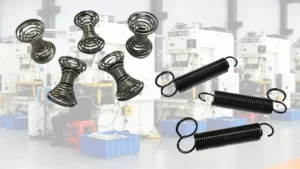
Compression and extension springs both store mechanical energy and return it when a load changes, but they work in opposite directions. A compression spring resists being pushed shorter, while an extension spring resists being pulled longer. Choosing between them requires more than comparing size and price: working loads, available space, end configurations, fatigue life, and installation conditions all affect performance.
This guide compares compression and extension springs, explains their working principles and common failure modes, and provides a practical framework for selecting, installing, and testing the right spring for your application.
Quick Answer: Compression vs Extension Springs at a Glance
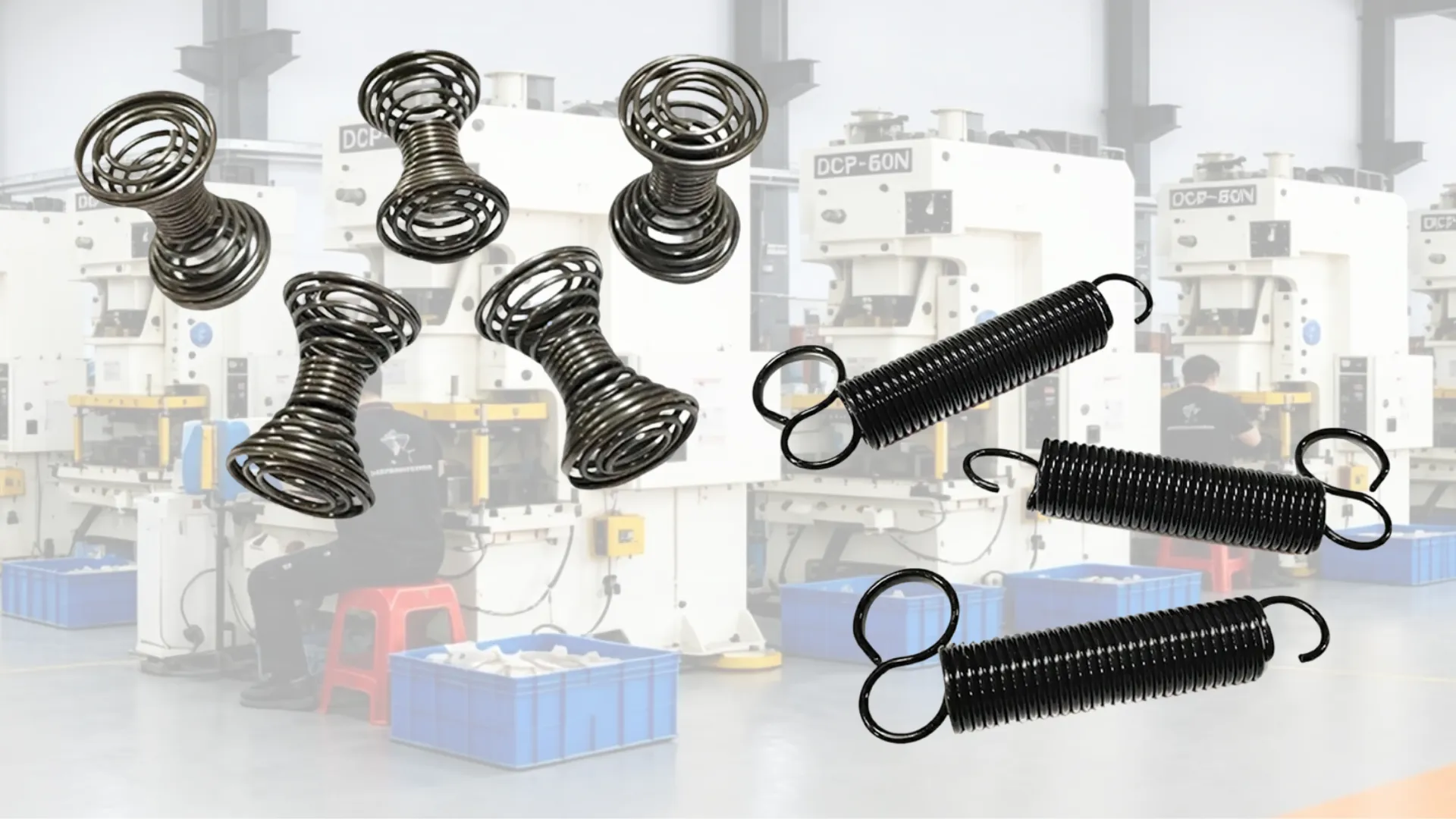
The main difference is the direction of the applied force. A compression spring pushes back when compressed, whereas an extension spring pulls back when stretched. Compression springs often have simpler end configurations and can be economical for axial loading. Extension springs are useful when two attachment points need to be pulled together, but their hooks or loops require careful design because these areas can experience high local stresses.
| Comparison | Compression Spring | Extension Spring |
|---|---|---|
| Force direction | Resists compression and pushes back | Resists extension and pulls back |
| Unloaded coil condition | Usually has gaps between active coils | Usually has closely wound coils in contact |
| End configuration | Open, closed, or closed and ground ends | Machine hooks, crossover hooks, loops, or custom ends |
| Initial tension | Not normally defined as an extension-spring initial-tension parameter | Often has built-in initial tension that must be overcome before extension begins |
| Typical cost | Often lower for comparable, straightforward designs | May cost more because of end forming and additional design requirements |
| Typical applications | Valves, suspension systems, switches, and return mechanisms | Hinges, counterbalances, closures, and tensioning mechanisms |
Two important design warnings: Long compression springs can buckle sideways if their geometry and support conditions are unsuitable. Extension springs can develop fatigue cracks or permanent deformation at the hook-to-body transition, particularly when the load is misaligned.
What Is a Compression Spring?
Definition and Basic Working Principle
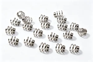
A compression spring is a mechanical spring designed to resist an axial compressive load. When two components push toward each other, the spring shortens and stores elastic energy. When the load decreases, it expands toward its original free length and pushes the components apart.
Most compression springs use a helical coil made from spring wire. Their performance depends on factors such as wire diameter, mean coil diameter, active coil count, material properties, and working deflection.
For a spring operating within its elastic range, the approximate force-deflection relationship is:
F = k × δ
Here, F is the applied force, k is the spring rate, and δ is the compression from the free length. A higher spring rate means that more force is required for the same amount of compression.
For example, a compression spring installed between two plates pushes against both plates when they move closer together. This makes it suitable for applications that require cushioning, preload, vibration control, or a restoring force.
Coil Spacing and End Configurations
Compression springs usually have visible gaps between their active coils in the unloaded state. These gaps provide room for the coils to move closer together under load. If the spring reaches solid height, the coils contact one another and further compression becomes highly restricted.
Common end configurations include:
- Open ends: The end coils continue the regular helix and may provide less stable seating in some applications.
- Closed ends: The end coils are brought closer together to create a more suitable seating surface.
- Closed and ground ends: The ends are ground to improve squareness and contact with flat seats, where the design and wire size permit.
End geometry affects seating stability, load alignment, available solid height, and the risk of uneven loading. A spring that is poorly seated can tilt or develop lateral movement even when its nominal spring rate is correct.
Common Applications
Compression springs are widely used wherever a mechanism needs a controlled pushing force or a means of returning to its original position. Common examples include:
- Automotive suspension and vibration-control systems.
- Valves, pumps, and pressure-control mechanisms.
- Door closers and mechanical return mechanisms.
- Keyboard switches, push buttons, and electrical contacts.
- Industrial presses, fixtures, and tooling assemblies.
- Mattresses, seating systems, and cushioning equipment.
The correct spring depends on the required force, stroke, available installation space, operating temperature, cycle count, and whether the spring needs a guide or protective enclosure.
What Is an Extension Spring?
Definition and Basic Working Principle
An extension spring is designed to resist an axial tensile load. When two attachment points move apart, the spring extends and develops a restoring force that pulls the attachment points back toward each other.
Most helical extension springs have closely wound coils in their unloaded state. The wire coils are commonly in contact, and the spring may incorporate initial tension from the manufacturing process. This built-in force helps keep the spring closed until a sufficient external load is applied.
Unlike a compression spring that pushes against two seats, an extension spring generally transfers its force through hooks, loops, or other end connections. The strength of these connections is therefore part of the spring’s overall performance, not merely a mounting detail.
Hook/Loop End Types and Initial Tension
Extension springs can use several end configurations, including:
- Machine hooks: Hooks formed from the end of the spring wire for attachment to a pin or similar feature.
- Crossover hooks: Hooks formed with a crossover geometry that may suit particular attachment and loading arrangements.
- Side hooks: Hooks oriented to one side of the spring body to meet a specific installation requirement.
- Extended hooks and loops: Longer or specially shaped ends used to accommodate attachment geometry, clearance, or assembly requirements.
- Custom ends: Formed ends designed around the available mounting space and expected load direction.
The transition between a hook and the spring body is a critical design area. Changes in wire curvature and loading direction can create stress concentrations, and a hook that is too small, poorly aligned, or unsuitable for the load can fail before the coil body reaches its fatigue limit.
Initial tension is the force required to begin separating the closely wound coils of an extension spring. Once this force is overcome, the spring extends further as the applied load increases.
A simplified force relationship after extension begins is:
F ≈ Fᵢ + k × x
Here, Fᵢ represents the initial tension, k is the spring rate, and x is the extension beyond the reference point at which the initial tension has been overcome. Actual force-deflection behavior depends on the spring design and measurement reference.
Initial tension should be specified or verified when the mechanism needs a defined pull at the beginning of its movement. It should not be assumed from the spring’s outside dimensions alone.
Common Applications
Extension springs are suitable for mechanisms that need to pull two components together or maintain tension between moving parts. Typical applications include:
- Screen doors and other self-closing mechanisms.
- Garage door counterbalance systems designed around extension springs.
- Trampolines and selected exercise equipment.
- Mechanical clutches and tensioning assemblies.
- Safety stops and return mechanisms.
- Hinges, latches, and moving linkages that require a restoring pull.
For applications involving people, overhead doors, or stored mechanical energy, the complete assembly needs appropriate retention and safety provisions. A spring’s nominal load rating alone does not establish that the mechanism is safe. For custom configurations and hook options, see extension springs.
Compression vs Extension Springs: Direct Comparison Table
The following table summarizes the main engineering and purchasing differences. The comparison assumes broadly similar spring materials and general manufacturing quality; actual performance depends on the specific dimensions, load requirements, and installation conditions.
| Factor | Compression Spring | Extension Spring |
|---|---|---|
| Force direction | Pushes back against compression | Pulls back against extension |
| Unloaded coil state | Normally separated by gaps | Normally close-wound and in contact |
| End configuration | Closed, open, or ground seating ends | Hooks, loops, crossover ends, or custom attachments |
| Initial tension | Usually specified through installed compression and preload conditions | Often an inherent design parameter that affects the starting force |
| Load capacity | Can provide substantial axial loads within its stress and stability limits | Limited by the coil body, initial tension, hooks, and attachment geometry |
| Manufacturing complexity | Often relatively straightforward for standard designs | Requires appropriate end forming and hook or loop stress evaluation |
| Typical unit cost | Often economical for simple, standard configurations | May be higher when custom hooks or demanding fatigue requirements are needed |
| Installation sensitivity | Seating, alignment, lateral stability, and buckling matter | Hook orientation, anchor alignment, clearance, and side loading matter |
| Common failure locations | Coil body, end transitions, or contact and wear areas | Hook-to-body transitions, hooks, and coil body |
| Potential consequence of breakage | May retain some support in a constrained assembly, but this must be validated | Often loses its intended tensile restoring force when the load path breaks |
Important qualification: Neither spring type is universally stronger, cheaper, or safer. Load capacity must be evaluated at the required working position, and failure consequences depend on the surrounding mechanism. A broken compression spring can jam an assembly or release stored energy, while an extension spring can recoil or allow a suspended component to move unexpectedly.
Mechanical Behavior: The Core Engineering Difference
Force–Deflection Curve: Linear vs Pre-Tensioned
For a conventional compression spring operating within its elastic range, force generally increases approximately linearly with compression. If the spring rate is 10 N/mm, for example, an additional 2 mm of compression requires approximately 20 N of additional force, assuming the spring remains within its intended operating range.
The relationship can be expressed as:
F = k × δ
This simplified equation does not account for nonlinear behavior near solid height, geometric changes, friction, buckling, or material yielding.
An extension spring with initial tension behaves differently near its unloaded state. The force must first overcome the built-in initial tension before the coils begin to separate. After that point, the force generally rises with further extension.
For engineering calculations, distinguish between the initial tension, the spring rate, and the load at the actual installed length. Using the spring rate alone can produce an incorrect estimate of the force delivered by an extension spring.
Several variables affect the spring rate and available force:
- Wire diameter: A relatively small change can substantially affect stiffness and stress.
- Mean coil diameter: Changes spring flexibility and the stress generated by a given load.
- Active coil count: More active coils generally produce a lower spring rate when other variables remain constant.
- Material properties: The shear modulus and allowable stress affect calculated performance.
- Working travel: The required stroke determines the operating force range and stress level.
Load Distribution and Stress Concentration
In a well-designed compression spring, the load is transmitted through the coil body and into the end seats. The wire still experiences torsional stress, and local stresses can develop near the ends or at contact points. Uneven seating, rubbing, corrosion, and lateral deformation can further affect fatigue life.
Extension springs also experience stress in the coil body, but the hooks introduce additional bending and stress concentration. The hook geometry, inside radius, wire diameter, load direction, and attachment point all affect the local stress state.
This is why two extension springs with similar coil dimensions can have different fatigue performance if their hooks are designed differently. It is also why a hook that fits a mounting pin is not automatically suitable for repeated loading.
For both spring types, the objective is to keep working stresses within appropriate design limits while accounting for the actual load spectrum, material, manufacturing process, environment, and required cycle life.
Durability and Failure Modes: Which Type Lasts Longer?
Neither compression nor extension springs are inherently more durable in every application. Durability depends on stress, geometry, material, surface condition, manufacturing quality, load cycles, and installation. The most useful comparison is therefore based on the failure mechanisms expected in the intended assembly.
Compression Spring Failure Modes
Compression springs can fail in several ways:
- Fatigue fracture: Repeated stress cycles can initiate and propagate cracks in the wire, particularly where local stresses are high.
- Permanent deformation or set: Excessive stress or unsuitable operating conditions can cause the spring to lose free length or force.
- End wear: Repeated contact with seats can cause wear, fretting, or damage to coatings.
- Buckling: A slender spring can bend sideways under compression, causing rubbing, uneven loading, and premature failure.
- Corrosion: Moisture, chemicals, or other environmental exposure can reduce the effective wire section and accelerate fatigue.
Preventive measures include checking stress at the required working loads, avoiding excessive compression, selecting suitable materials and finishes, providing stable end seats, and evaluating whether a guide is necessary.
Extension Spring Failure Modes
Common extension spring failures include:
- Hook fatigue: Repeated bending and tensile loading can initiate cracks at the hook-to-body transition.
- Hook opening or fracture: An overloaded or unsuitable hook can deform or break, interrupting the tensile load path.
- Initial tension loss: The spring may no longer maintain its intended starting force after excessive stress or permanent deformation.
- Permanent elongation: Overextension can leave the spring longer and change its operating characteristics.
- Coil-body fatigue: The main helical body can also crack under repeated loading, particularly if the stress range is too high.
- Corrosion and wear: Environmental damage can reduce fatigue resistance, especially at highly stressed surfaces.
Hook design, proper anchoring, accurate initial-tension control, and avoiding overextension are central to reliable extension spring operation.
Why Extension Spring Hooks Are Often the Weakest Link—and How to Reduce Risk
The hook must redirect the load from the spring’s axial coil body into an attachment point. This change in geometry creates a region where bending stress can be considerably higher than in the body of the spring.
If the mounting points are not aligned, the hook may also experience side loading or twisting. Repeated off-axis loading can accelerate fatigue, even if the spring body appears to be operating within its intended extension range.

When an extension spring repeatedly breaks at the hook, inspect the complete load path rather than simply replacing the spring with a heavier one. Check the following:
- Whether the spring axis aligns with the direction of the applied load.
- Whether the hook radius and cross-section are appropriate for the working force.
- Whether the hook contacts a sharp edge or an attachment point that causes local wear.
- Whether the spring is being extended beyond its specified working length.
- Whether the hook orientation changes during the operating cycle.
| Condition | Typical symptom | Engineering consequence | What to check |
|---|---|---|---|
| Aligned axis, matched hook type | Lower bending stress at the hook; predictable fatigue life | Load transfers along the coil axis | Hook radius, wire diameter, working length |
| Misaligned anchor / side loading | Hook carries both tension and bending; stress concentrates at the transition | Hook cracks before the coil body fatigues | Whether the spring axis matches the load direction |
| Hook contacting a sharp edge / insufficient clearance | Local wear and coating damage | Worn area becomes a crack initiation site | Contact surface, clearance, whether hook orientation changes during cycling |
A crossover hook, extended hook, swivel attachment, or custom end may improve performance when it better matches the load direction and mounting geometry. However, no hook type is universally superior under all off-axis conditions. The complete geometry must be evaluated.
For example, a spring used in a repeatedly cycled linkage may continue to fail when a standard hook is pulled sideways. Correcting the mounting alignment or redesigning the end connection may be more effective than increasing the wire diameter alone.
Practical rule: If the hook keeps breaking, investigate hook geometry, alignment, and stress before assuming that the coil body needs to be stronger.
Failure Consequences: What Happens After Each Spring Breaks?
A broken spring can have different consequences depending on how the mechanism contains and supports it.
When a compression spring fractures inside a constrained assembly, the remaining pieces may still provide some mechanical resistance or limited support. This is possible only under suitable conditions. Broken coils may shift, interlock, jam the mechanism, damage nearby components, or cause the assembly to lose its intended force.
An extension spring typically relies on a continuous tensile load path between its attachment points. If the spring body or a hook breaks, the intended pulling force is usually lost. A door, linkage, tensioner, or counterbalance may then move into an unintended position.
These differences can affect decisions for equipment that is difficult to access, expensive to stop, or safety-critical. However, a compression spring must not be treated as a fail-safe support merely because its fragments may remain trapped in the assembly.
Where continued support after spring failure is necessary, engineers should design and validate an independent retention or load-bearing feature. The assembly should be tested under realistic failure conditions rather than relying on the spring’s expected behavior after fracture.
Durability Comparison Under Real Conditions
Compression springs often have an advantage when a straightforward axial pushing force is required and stable seating or guidance is available. Extension springs can be equally appropriate when the mechanism requires a pulling force and the end connections are correctly designed.
A compression spring may be the better choice when:
- The application requires repeated axial compression.
- The spring can be seated and guided reliably.
- The working stress and compression travel remain within the design limits.
An extension spring may be the better choice when:
- The mechanism naturally pulls two attachment points apart during operation.
- The spring needs to provide a return force through hooks or loops.
- Initial tension is useful and the end connections can be protected from excessive side loading.
For either type, specify the required cycle life, working loads, maximum travel, operating environment, and acceptable change in force. These requirements provide a more meaningful basis for durability comparison than spring type alone.
Cost, Manufacturing, and Commercial Considerations
Unit Cost and Tooling Complexity
Compression springs are often economical because common helical designs can be produced using established winding processes, with relatively straightforward end finishing. Standard dimensions and readily available materials can further reduce manufacturing and procurement costs.
Extension springs require coil winding and end forming. Depending on the design, additional work may be needed to control hook geometry, orientation, initial tension, and fatigue performance. These requirements can increase setup time, inspection effort, and unit cost.
However, neither type has a fixed price advantage. A complex compression spring with tight tolerances, unusual end geometry, special material, or demanding fatigue requirements can cost more than a simple extension spring.
It is not reliable to claim that extension springs always cost three to five times as much as compression springs. Any such multiplier depends on the specific parts being compared, order quantity, manufacturing method, tolerances, and testing requirements.
For a meaningful quote comparison, provide the spring dimensions, material, required load at working positions, expected cycle life, surface finish, annual quantity, and inspection requirements.
Total Cost of Ownership
The purchase price is only one part of the cost of a spring-based mechanism. A lower-cost spring can become expensive if it requires additional components, frequent replacement, or repeated maintenance.
Consider the following cost factors:
- Installation labor: Does the spring require special tools, precise alignment, or difficult access?
- Replacement and downtime: How much does it cost to stop the equipment and replace a failed spring?
- Additional components: Does the selected spring require levers, cables, guides, sleeves, or extra brackets?
- Testing and inspection: Are additional fatigue, load, or end-connection tests needed?
- Space-related redesign: Does the spring’s shape require changes to the housing or mounting points?
- Safety provisions: Are restraints or secondary supports needed to control the consequences of failure?
A spring with a slightly higher unit cost may reduce total cost if it eliminates unnecessary linkage components or improves service life. Conversely, a custom spring may not be economical when a standard design already meets the functional requirements.
How to Choose: Decision Guide by Application
Use Compression Springs When…
A compression spring is generally a suitable starting point when:
- The mechanism needs a pushing force or must resist components moving closer together.
- The available space accommodates the required free length and compression travel.
- The spring must support a specified axial load without exceeding allowable stress.
- The application benefits from straightforward end seating and economical manufacturing.
- A guide rod, bore, or other suitable restraint can be provided when needed to control lateral instability.
Before selecting the spring, check the load at each working length, maximum compression, solid height, stress, and potential for buckling. Do not assume that a spring will remain stable simply because it fits inside the available space.
Use Extension Springs When…
An extension spring is generally a suitable starting point when:
- The mechanism needs to pull two attachment points toward each other.
- The spring can be mounted between suitable anchors.
- Initial tension is useful for maintaining contact or providing a defined starting force.
- The available space accommodates the spring body, hooks, and full extension range.
- The mounting arrangement can control alignment and avoid unacceptable side loading.
Check the force at the installed length, the initial tension, the maximum extension, and the strength of the end connections. The spring must not be selected solely by its free length or outside diameter.
Is the Mechanism Pushing or Pulling? Make This Decision First
One of the most important early decisions is determining how the mechanism naturally moves. Select the spring based on the required force direction before designing additional hardware around it.
Imagine an exercise machine that needs to resist a user’s pulling motion. If the design uses compression springs, the mechanism may need cables, pulleys, or levers to convert the user’s pulling motion into compression of the springs. This arrangement can work, but it may add weight, friction, assembly complexity, and additional failure points.
An extension spring may provide a more direct resistance force if the geometry allows the spring to be stretched safely. The overall design could become simpler, but the extension spring’s hooks, initial tension, and fatigue life would still need to be verified.
The opposite problem can also occur. If a mechanism naturally compresses a spring, using an extension spring may require extra attachment space and a different load path. The hooks may interfere with nearby components, and the spring may not deliver the desired force profile.
Start with the relative movement of the two connection points. Determine whether they move toward each other or away from each other during the working cycle. Then choose a spring type that produces the required restoring force with the least unnecessary mechanical complexity.
Decision Checklist
Use the following checklist before specifying or ordering a spring:
- Force direction: Does the mechanism require a pushing force or a pulling force?
- Available space: What are the maximum and minimum installed lengths, diameters, and clearances?
- Load and deflection: What force is required at each working position, and what is the total travel?
- Initial tension: Does the mechanism require a defined pull before appreciable extension occurs?
- End connections: Are the seats, hooks, loops, pins, and anchor points compatible with the load direction?
- Alignment: Can the spring operate without excessive side loading or rubbing?
- Stability: Does a compression spring need a guide rod, bore, or sleeve?
- Fatigue life: How many cycles must the spring withstand, and what constitutes an unacceptable loss of force?
- Environment: Are corrosion resistance, temperature resistance, or special materials required?
- Cost and validation: What are the target unit cost, order quantity, and required acceptance tests?
Initial tension deserves particular attention in extension spring calculations. If the design assumes that the spring force starts at zero and increases only according to the spring rate, the actual force may differ significantly from the expected value. Specify the required initial tension and verify the force at the operating positions.
Installation, Interchangeability, and Common Misuse
Compression Spring Buckling: A Design Risk That Must Be Checked Early
Buckling occurs when a compression spring deflects laterally rather than shortening along its intended axis. The risk increases when the spring is long relative to its mean coil diameter, particularly when the ends are poorly restrained or the spring has a large working deflection.
A free-length-to-mean-diameter ratio around four is often used as an initial screening indicator. It is not a universal buckling threshold: actual stability depends on end conditions, spring geometry, deflection, and the surrounding structure. A spring with a ratio below four can still require a stability check, while some longer springs can operate successfully with suitable support.

| Condition | No guide | Guide rod / sleeve |
|---|---|---|
| High slenderness ratio | Prone to lateral bending, rubbing, and uneven loading | Limits lateral displacement and improves stability |
| Poor end restraint | Tends to tilt | Improves end seating |
| Guide clearance | — | Must allow for tolerances and coil diameter change during compression |
When a spring begins to buckle, it may rub against nearby components, produce noise, wear its surface, deliver an inconsistent axial force, or fail prematurely. The lateral movement can also create a load path that the original design did not anticipate.
Common ways to control buckling include:
- Internal guide rod: A rod passes through the spring’s inside diameter to limit lateral movement.
- External bore or sleeve: A surrounding structure helps keep the spring aligned.
- Geometry changes: Adjusting the free length, mean coil diameter, or spring arrangement can improve stability.
- Improved end support: Appropriate seating and end geometry can reduce the tendency to tilt.
Guides require adequate clearance for dimensional tolerances and changes in coil diameter during compression. Excessive contact can introduce friction and wear, so the guide must be designed as part of the complete assembly.
For applications where post-fracture behavior matters, aerospace design guidance such as NASA-STD-5017 discusses spring design and the importance of restraint against buckling. The appropriate requirements should be confirmed against the applicable revision and the specific application.
If the available space cannot accommodate a guide, reconsider the spring geometry or the overall mechanism. The correct question is not simply whether a compression or extension spring fits, but whether the selected design can operate reliably within the actual constraints.
Extension Spring Installation Traps
Extension springs can fail early even when their nominal force rating appears adequate. Common installation problems include:
- Incorrect hook orientation: The hooks may twist or experience additional bending during operation.
- Anchor misalignment: The load may pull the spring sideways rather than along its axis.
- Incorrect initial tension: The spring may not provide the required force at the start of movement.
- Insufficient clearance: Hooks may rub against the housing or interfere with adjacent components.
- Overextension: Excessive travel can cause permanent elongation, hook deformation, or fatigue damage.
Before installation, compare the actual attachment geometry with the spring drawing. Check the installed length, working length, hook orientation, load direction, and maximum extension. A spring that fits physically is not necessarily interchangeable with the original.
Can You Use a Compression Spring Where an Extension Spring Was Designed?
Sometimes a mechanism can be redesigned to use a different spring type, but the substitution should be evaluated at three separate levels.
1. Functional interchangeability. Does the new spring provide the required force in the direction of movement? A compression spring cannot directly pull two separated attachment points together without an additional mechanism that changes the load path.
2. Interface interchangeability. Can the replacement fit the available space and connect to the existing mounting points? Compression springs usually need suitable seats, while extension springs use hooks or loops. The change may affect axial length, radial clearance, alignment, and surrounding components.
3. Life and safety interchangeability. Does the modified assembly maintain acceptable stress, fatigue life, retention, and failure behavior? A design that works during a short bench test may still fail after repeated cycles.
Manually bending the end of a compression spring into a 90-degree hook or attaching improvised wire loops may create local stress concentrations and unpredictable fatigue performance. Such modifications should not be treated as validated replacements for parts with defined service-life or safety requirements.
Similarly, using an extension spring as a compression spring is not a straightforward reversal. Its initial tension, coil arrangement, end geometry, and stability may not be suitable for compressive loading.
For a properly engineered alternative, consider redesigning the load path or using a purpose-designed spring arrangement. Drawbar springs are one example of a commercial configuration that can provide a compression-spring-like load path with a tensile spring arrangement, depending on the design. The specific spring and assembly must still be selected for the required load and travel.
NASA-STD-5017 provides relevant engineering guidance on spring arrangements, including the use of compression-spring alternatives in some extension-spring applications. It should be treated as design guidance for applicable systems, not as blanket approval for an improvised conversion.
Testing and Validation Considerations
Compression and extension springs require different validation priorities because their force directions, end conditions, and common failure mechanisms differ. A test plan should reflect the actual operating cycle and assembly rather than evaluating the spring in isolation.
Compression Spring Testing
Typical compression spring checks include:
- Load-deflection testing: Measure the force at specified compressed lengths.
- Free-length inspection: Verify the unloaded length against the drawing.
- End squareness and parallelism: Check whether the ends seat properly under load.
- Solid-height and travel checks: Confirm that the spring does not reach an unacceptable compressed condition during normal operation.
- Fatigue testing: Evaluate performance over the required number of operating cycles.
- Permanent-set measurement: Determine whether free length or load performance changes after cycling.
- Buckling evaluation: Verify lateral stability under the intended end conditions and guide arrangement.
Where a guide rod or sleeve is used, test the spring in the intended assembly. Guide clearance, friction, and contact can affect the delivered force and wear pattern.
Extension Spring Testing
Typical extension spring checks include:
- Initial-tension measurement: Verify the force required to begin separating the coils.
- Load-extension testing: Measure force at specified lengths throughout the working range.
- Hook and loop inspection: Check dimensions, orientation, forming quality, and attachment compatibility.
- End-connection strength: Verify that hooks and loops can withstand the specified operating load.
- Hook fatigue testing: Evaluate the ends under representative cyclic loading, including foreseeable misalignment where relevant.
- Permanent-elongation checks: Measure changes in free length, initial tension, and force after cycling.
For demanding applications, the test fixture should reproduce the real attachment geometry. A hook tested under ideal axial alignment may behave differently in service if the actual mounting points introduce side loading.
Why Test Plans Cannot Be Interchanged
Both spring types need dimensional inspection, force verification, and durability assessment, but the acceptance criteria should reflect their distinct operating behavior.
Extension springs require explicit attention to initial tension, hook geometry, end strength, and fatigue at the end transitions. Compression springs require explicit attention to solid height, end seating, lateral stability, and behavior under the intended guide conditions.
A meaningful validation plan should specify the test loads, working positions, cycle count, test speed where relevant, environmental conditions, and allowable changes in force or dimensions. Safety-critical applications may require additional qualification, redundancy, and failure testing.
Real-World Example: A Selection Failure and What It Teaches
Case A: An Extension Spring That Repeatedly Breaks at the Hook
Consider a mechanism that uses an extension spring to return a moving component to its starting position. The spring fits the available space and produces the required nominal pull, but the hook repeatedly fractures after a relatively short period of operation.
Replacing the spring with another unit of the same dimensions does not resolve the problem. Inspection reveals that the attachment points are slightly misaligned, causing the hook to experience bending in addition to the intended tensile load.
The engineering response is to evaluate the complete load path, confirm the working extension, and redesign the hook or mounting interface. Depending on the geometry, a crossover hook, extended hook, swivel connection, or custom end may be appropriate. If the mechanism can be redesigned, a compression spring arrangement may also be considered.
The lesson is that repeated hook failure should trigger an investigation into alignment and end geometry rather than an automatic increase in spring size.
Case B: Compression Springs Used in a Pulling Mechanism
Imagine an exercise device that must resist a user’s pulling motion. The original concept uses compression springs to generate resistance, so the mechanism incorporates cables, levers, and additional supports to convert the pulling movement into compression.
The design may function, but the added hardware increases part count, assembly complexity, friction, and the number of components that can wear or fail. The spring arrangement also takes up space that could potentially be used more efficiently.
An extension spring may offer a more direct solution if the attachment points can safely move apart during the operating cycle. Switching spring types would still require checking the required force profile, initial tension, hook strength, and fatigue life. The goal is not to replace a spring without analysis, but to simplify the mechanism while preserving performance.
Three Rules to Remember
- Choose the force direction first. Determine whether the mechanism needs to push or pull before selecting the spring type.
- Design extension spring ends as load-bearing features. Hook geometry, alignment, and fatigue resistance matter as much as the coil body.
- Check compression spring stability before finalizing the layout. Confirm that the spring can operate without unacceptable buckling, rubbing, or instability.
These examples illustrate common engineering problems rather than documented results from a specific customer project. Actual redesign decisions should be supported by load calculations, drawings, and validation testing.
Frequently Asked Questions
1. What Is the Main Difference Between Compression and Extension Springs?
A compression spring resists being pushed shorter and produces a restoring force that pushes components apart. An extension spring resists being pulled longer and produces a restoring force that pulls attachment points together. Their end configurations and typical failure mechanisms also differ.
2. Which Spring Is Stronger, Compression or Extension?
Neither type is universally stronger. Load capacity depends on wire diameter, coil diameter, material, working deflection, allowable stress, end geometry, and installation conditions. For extension springs, hook strength and initial tension can limit performance. For compression springs, stress and buckling can limit the usable load.
3. Are Extension Springs More Expensive Than Compression Springs?
Extension springs can cost more when hook forming, initial-tension control, and end inspection add manufacturing complexity. However, price depends on the specific design, order quantity, material, tolerances, and testing requirements. A reliable comparison requires quotations for parts with equivalent performance requirements.
4. Can a Compression Spring Be Used as an Extension Spring?
Not as a direct, like-for-like replacement. A compression spring pushes against its seats rather than directly pulling two attachment points together. Conversion usually requires a redesigned load path or a purpose-designed alternative, followed by checks of interfaces, stress, fatigue, and safety.
5. Which Type Is More Durable?
Durability depends on the operating conditions and design quality. Compression springs must be checked for fatigue, permanent set, and buckling. Extension springs require careful control of hook stress, initial tension, alignment, and maximum extension. The better choice is the one that meets the required service life under the actual load cycle.
6. Why Do Extension Springs Fail at the Hook?
The hook changes the direction of the load and creates a stress concentration near the hook-to-body transition. Misalignment, unsuitable hook radii, excessive extension, wear, or repeated side loading can accelerate fatigue. Inspect the attachment geometry and working conditions before changing the spring specification.
7. Do Compression Springs Buckle, and How Do You Prevent It?
Yes. A compression spring can bend sideways when its geometry, deflection, and end support create insufficient lateral stability. A guide rod, surrounding bore, suitable end seating, or revised spring geometry can reduce the risk. A free-length-to-mean-diameter ratio near four is a useful preliminary screening indicator, not a universal pass-or-fail rule.
8. What Happens When a Compression Spring Breaks Compared With an Extension Spring?
A broken compression spring may retain some resistance if its fragments remain constrained, but it can also jam or lose its intended function. A broken extension spring usually loses its tensile restoring force because the load path is interrupted. The actual consequence depends on the assembly, so critical systems need independent retention or fail-safe provisions.
9. Do Extension Springs Have Initial Tension?
Many extension springs have initial tension created during manufacture. This is the force needed to start separating their closely wound coils. The initial tension affects the starting force and should be included when specifying the spring’s operating loads.
10. How Can You Identify Compression and Extension Springs Visually?
A compression spring usually has visible gaps between its coils and ends shaped to seat against supporting surfaces. An extension spring usually has closely wound coils and hooks or loops at its ends. Visual appearance is a useful first check, but a drawing or force test is preferable when the spring’s function is uncertain.
11. Which Spring Is Better for Tight Spaces?
It depends on the direction of movement and the available installation envelope. Extension springs can work well in compact pulling mechanisms, but their hooks need clearance and suitable anchors. Compression springs can also fit compact assemblies, provided there is enough room for the required travel and any necessary guidance.
12. How Are Compression and Extension Springs Tested Differently?
Both types need dimensional, force, and durability checks. Compression spring testing emphasizes load-deflection behavior, free length, solid height, end seating, and buckling. Extension spring testing emphasizes initial tension, load-extension behavior, hook strength, end alignment, and fatigue at the hook transitions.
Conclusion and Next Step
Compression and extension springs serve different mechanical functions, and neither is the best choice for every application. Compression springs are suitable for pushing forces and require attention to working stress, seating, and lateral stability. Extension springs are suitable for pulling forces and require particular attention to initial tension, hook geometry, and alignment.
The most reliable selection process begins with the mechanism’s movement direction, followed by the available space, required load and travel, service life, installation conditions, and consequences of failure. Price should be evaluated only after the functional and engineering requirements are clear.
Before requesting a custom spring, prepare the available dimensions, required force at working positions, maximum travel, operating cycle, material or environmental requirements, and expected service life. For compression springs, include the available guide or bore dimensions. For extension springs, include the attachment drawing, hook orientation, installed length, and required initial tension.
These details make it easier to evaluate manufacturability, compare suitable designs, and validate that the selected spring will perform reliably in the finished mechanism.