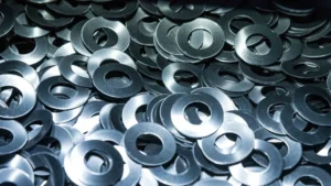
A disc spring is a conical, washer-shaped spring that produces an axial force when compressed. Also known as a Belleville spring or Belleville washer, it can generate relatively high loads within a short axial space, making it useful in bolted joints, valves, clutches, braking systems, and other mechanical assemblies.
Choosing the right disc spring involves more than matching its outside diameter and load rating. Its force-deflection behavior, material, operating temperature, fatigue requirements, surface protection, and installation conditions all affect performance. This guide explains how disc springs work, the main types and standards, how to select materials and dimensions, how to configure spring stacks, and which common design and installation problems to avoid. HESSP manufactures custom precision springs from 0.03–25 mm wire diameter for demanding OEM applications.
What Is a Disc Spring?
Definition and Basic Geometry
A disc spring is an annular spring component formed into a shallow cone. Unlike a flat washer, it has a measurable free cone height that allows it to deflect axially under an applied load. As the cone flattens, the spring develops a reaction force that can be used to maintain preload, absorb movement, or control the load transmitted through an assembly.
The main geometric parameters are:
- Outside diameter (OD): The diameter measured across the outer edge of the disc.
- Inside diameter (ID): The diameter of the central opening.
- Thickness (t): The material thickness of the disc.
- Free cone height (l0): The overall height of the unloaded conical disc, measured from the lower bearing plane to the upper surface at the center.
- Cone height above thickness (h0): The cone height above the disc thickness, commonly used in disc spring calculations. It is related to the overall free height by h0 = l0 − t.
- Deflection (s): The axial displacement from the unloaded position under an applied load.
The ratio between cone height and thickness, h0/t, has a significant influence on the load-deflection curve. Two disc springs with similar outside diameters can therefore behave differently if their thicknesses or cone heights differ.
Disc Spring vs. Belleville Washer: What’s the Difference?
The terms disc spring, Belleville spring, and Belleville washer are frequently used interchangeably. In general engineering usage, they refer to the same basic conical spring geometry.
The term Belleville washer is particularly common in fastening applications, where the component is used to maintain a clamping force or accommodate small changes in joint length. Disc spring is a broader term used in spring design and industrial engineering, including applications that require defined force-deflection characteristics and fatigue performance.
However, not every conical washer is a precision disc spring. A conventional conical washer may be designed primarily for fastening or load distribution, whereas an engineered disc spring is selected according to its spring characteristics, dimensional tolerances, material properties, and intended duty cycle.
In practice, the distinction often comes down to application intent and specification rigor. Belleville washers are predominantly used in heavy-duty bolted joints where the load is treated as static, and some products sold under this name are manufactured from lower-grade materials without adherence to close tolerances, which can produce larger variations in load-deflection behavior. Precision disc springs, by contrast, are specified with defined force-deflection data, material grade, and tolerance class for applications requiring a repeatable force-travel relationship, including dynamic or cycling duty. When a component is described only as a “Belleville washer,” its actual load curve, fatigue capability, and dimensional conformance should be confirmed rather than assumed to match a precision disc spring.
When comparing components, check their actual dimensions, load-deflection data, material specifications, and applicable standards rather than relying on the product name alone.
Common Aliases and Terminology
Common names and related terms include:
- Disc spring: The general engineering term for a conical spring disc.
- Belleville spring: A widely used alternative name for a disc spring.
- Belleville washer: A term frequently encountered in bolted-joint and fastening applications.
- Conical spring washer: A descriptive term for a washer-shaped component with a conical profile.
- Disc spring stack: An assembly of multiple disc springs arranged to achieve a required force and deflection.
- Preload: The force already acting on a spring before the system reaches its maximum operating load.
- Scragging or presetting: A controlled initial loading process intended to reduce subsequent permanent settling or set.
These terms overlap, but they do not always imply identical manufacturing requirements. Technical specifications should define the intended geometry, performance, and quality requirements explicitly.
How Disc Springs Work
Conical Geometry and Axial Load
A disc spring works by resisting the change in its conical shape. When an axial compressive force is applied, the cone height decreases and elastic stresses develop within the material. The spring generates a reaction force that opposes further compression.
As the applied force increases, the disc progressively flattens. Its response depends on its geometry, elastic modulus, material properties, and boundary conditions. Because the load-deflection relationship is nonlinear in many designs, a given increase in deflection does not necessarily produce a constant increase in force.
When the load is removed, an elastically operating disc spring returns toward its original shape. If the stress exceeds the material’s elastic capability, however, permanent deformation can occur. Repeated loading can also initiate fatigue cracks, particularly around highly stressed regions such as the inner or outer edges.
Load-Deflection Curve Basics
A load-deflection curve describes the relationship between the axial force applied to a disc spring and the resulting displacement. It is one of the most important references for selecting a spring and evaluating its operating range.
The shape of the curve depends largely on the ratio of cone height to material thickness, together with the spring’s other dimensions and material properties. Depending on its geometry, a disc spring can exhibit a relatively steep, progressive, or more strongly nonlinear force response.
Several points on the curve are especially important:
- Initial deflection: The spring begins to compress and develops a reaction force.
- Intermediate deflection: The spring operates within its intended working range, where calculated and measured behavior can be more predictable.
- High deflection: As the spring approaches a flattened condition, stresses and force characteristics can depart substantially from simple design expectations.
- Flattened condition: The cone has almost completely collapsed. This is not automatically a suitable normal operating position.
For many standard disc spring designs, a working deflection between approximately 15% and 75% of the available cone deflection is used as a general design guideline. The actual permissible range must still be verified against the spring’s specification and operating conditions.
FAQ: Why is a working deflection of 15%–75% often recommended? What happens if a disc spring is flattened?
The 15%–75% range is a commonly used guideline, not a universal requirement for every disc spring. Below approximately 15% deflection, manufacturing-related residual stresses and initial seating effects can cause measured behavior to differ from theoretical calculations. In cyclic applications, operating through this region may also produce unfavorable stress reversals at critical locations.
Above approximately 75% deflection, the force-deflection response can deviate more significantly from the calculated curve, and the stress may rise rapidly. The exact behavior depends on the spring geometry; flattening does not produce the same force response in every design.
Repeatedly compressing a spring to a flattened position can reduce fatigue life or cause permanent set if the resulting stresses exceed the design limits. For dynamic applications, the load range, preload, stress range, and required cycle life should be evaluated together. Some designs permit operation beyond the general guideline, but this requires appropriate engineering verification rather than assuming full flattening is harmless.
Why Disc Springs Provide High Force in a Small Space
Disc springs use a conical annular shape to generate substantial axial force without requiring the long body of a conventional helical compression spring. Their load capacity comes from the combination of material strength, disc thickness, diameter, and cone geometry.
This makes them useful where axial installation space is limited but a significant clamping or reaction force is required. They can also be stacked to adjust the overall force-deflection characteristics without changing the basic spring design.
However, a compact design does not automatically mean a better design. A spring that generates the required force but operates too close to its flattening position, experiences excessive stress, or lacks sufficient fatigue life may not be suitable for the application.
Types of Disc Springs
Standard Conical Disc Springs
Standard conical disc springs are the conventional form used in a wide range of industrial applications. They are available in different outside diameters, inside diameters, thicknesses, cone heights, and material grades.
Standardized dimensions and performance characteristics make these springs easier to specify and compare. When a standard size meets the load, deflection, temperature, corrosion, and fatigue requirements, it can simplify component selection and replacement.
The most appropriate design depends on the required force at the working deflection, available radial and axial space, and the spring’s expected operating cycle. A larger spring may reduce stress for a given load in some designs, while a thicker or taller cone may produce a different force-deflection response.
Slotted and Serrated Disc Springs
Slotted disc springs contain cuts or slots that divide part of the annular structure into flexible sections. The slots change the spring’s mechanical response and can reduce its effective stiffness compared with an otherwise similar unslotted component.
Slotted designs are used when a particular combination of deflection, force, or flexibility is required. Their geometry must be assessed carefully because slots introduce additional edges and local stress concentrations that can affect fatigue performance.
Serrated disc springs have teeth or serrations along specified edges or surfaces. Depending on the design, these features may support particular engagement, locking, or contact functions. Serrations should not be assumed to provide a universal anti-loosening effect; their suitability depends on the mating components, contact conditions, and joint design.
Slotted and serrated components are not interchangeable with standard disc springs simply because their outside dimensions are similar. Their load-deflection data and intended applications should be confirmed separately.
Stacked and Pre-Set Disc Spring Assemblies
Disc springs can be assembled in different orientations to achieve a required load and deflection. A single disc may provide enough force but insufficient travel, or enough travel but insufficient force. Stacking allows designers to adjust these characteristics.
In a parallel stack, multiple discs are nested in the same direction. This increases the theoretical force capacity while keeping the total deflection approximately equal to that of one disc.
In a series stack, adjacent discs face opposite directions. This increases the available deflection while keeping the theoretical force approximately equal to that of one disc.
Combined stacks use groups of parallel discs arranged in series. They provide a way to increase both force and travel, although the resulting behavior depends on the number of discs, contact friction, alignment, and operating conditions.
Pre-setting is a separate manufacturing operation in which a spring is deliberately loaded to reduce subsequent permanent settling. A pre-set spring is not the same thing as a spring that is simply installed with an operating preload. Both processes may be relevant to a design, but they serve different purposes.
Parallel stacks also introduce friction between adjacent discs, which provides a degree of inherent damping. This hysteresis can be beneficial in vibration or shock-related applications, but it also means the loading and unloading curves do not coincide, and the actual load-deflection response will differ from the idealized calculation.
Disc Spring Standards: DIN EN 16983 and DIN 2093 Explained
What the DIN Series and Groups Mean
DIN 2093 is a long-established reference for disc springs, and DIN EN 16983 is the European standard covering disc springs with specified quality requirements. DIN EN 16983 addresses the product requirements, while DIN EN 16984 covers the calculation of disc springs.
When a disc spring is described as conforming to a particular standard, the designation should be checked against the applicable edition and the manufacturer’s technical documentation. The standard helps establish a consistent basis for dimensions, tolerances, quality requirements, and comparison between components.
Standard disc springs are commonly categorized by dimensional characteristics and material thickness. For example, manufacturer catalogs based on the established DIN 2093 dimensional system often distinguish three thickness groups:
- Group 1: Thin disc springs, typically with thicknesses below 1.25 mm.
- Group 2: Disc springs with thicknesses from 1.25 mm through 6 mm.
- Group 3: Thicker disc springs, generally above 6 mm.
DIN EN 16983 specifies tolerances across four dimensions that directly affect interchangeability and performance: diameter (outside and inside), material thickness (t), free overall height (l0), and spring force (F) at a defined test deflection. For diameter, the standard commonly corresponds to h12 for outside diameter and H12 for inside diameter, unless a tighter tolerance is separately agreed. Thickness, free height, and spring-force tolerances are grouped by thickness class and become proportionally wider for thicker springs. This means that two springs described as “DIN EN 16983” can still differ in actual load if they fall into different tolerance bands or if the load was verified at different test heights. When comparing catalog values, the applicable tolerance class and the test deflection should be confirmed, not assumed.
The exact scope, dimensional limits, and classification details should be confirmed against the applicable standard edition rather than inferred from a supplier’s abbreviated catalog description.
Series designations, often identified as A, B, and C in standard-based catalogs, describe different geometric proportions. These proportions influence the cone-height-to-thickness ratio and the resulting force-deflection characteristics. A series designation should therefore be read together with the actual dimensions and performance data.
Why Standards Matter When Selecting a Disc Spring
Standards provide a common technical reference when comparing springs from different manufacturers, specifying replacement components, and designing assemblies that require predictable performance.
A standard-based selection can help establish:
- Dimensional and geometric requirements.
- Applicable manufacturing tolerances and quality expectations.
- A consistent basis for force-deflection calculations.
- Relevant material and inspection requirements.
- Documentation needed for procurement and component interchangeability.
However, standard conformity alone does not establish that a spring is suitable for every application. The required load, working deflection, fatigue life, temperature, corrosion exposure, surface condition, and assembly arrangement still need to be checked.
For critical applications, the specification should identify the applicable standard edition, the required material and finish, the working load and deflection, and any additional testing or documentation requirements. It should also distinguish standard conformity from any application-specific performance guarantee.
Materials and Surface Treatments for Disc Springs
Common Spring Steels
Spring steels are widely used for disc springs because they can provide high strength, elastic recovery, and useful fatigue performance when properly manufactured and heat-treated.
Common material categories include:
- High-carbon spring steel: Used in many standard disc spring designs where high strength is required and the environment allows suitable corrosion protection.
- Alloy spring steel: Alloying elements and appropriate heat treatment can provide the strength and mechanical properties required for more demanding applications.
- Other application-specific spring alloys: Selected where temperature, corrosion, or other operating conditions make conventional spring steels unsuitable.
Common specific grades illustrate the practical range. In alloy spring steel, 51CrV4 (1.8159 / UNS G61500) is one of the most widely used disc spring materials, with a typical modulus of elasticity of 206 GPa. In high-carbon spring steel, C67S (1.1231 / UNS G10700) is also common and shares the same typical modulus of 206 GPa. For corrosion-resistant requirements, 301 stainless steel (X10CrNi18-8 / 1.4310) has a lower typical modulus of approximately 190 GPa, while precipitation-hardening 17-7 PH (X7CrNiAl17-7 / 1.4568) is approximately 200 GPa. The modulus difference matters: a stainless grade selected for corrosion resistance may produce a different load at the same deflection than a carbon or alloy steel spring of identical geometry, so material substitution should be accompanied by a load-deflection check rather than a dimensional swap alone.
Material selection should consider more than the nominal strength. Heat treatment, hardness, residual stress, surface quality, manufacturing processes, and the operating stress range can all influence fatigue life and resistance to permanent deformation.
For a dynamically loaded spring, a material with high tensile strength is not automatically the best choice if its surface condition, heat treatment, or corrosion resistance is inadequate for the application. HESSP also produces custom flat springs and stamped spring components for applications where the spring geometry differs from a standard disc profile.
Stainless and Corrosion-Resistant Options
Stainless steel and other corrosion-resistant materials may be appropriate when disc springs operate in humid, wet, chemically exposed, or otherwise corrosive environments.
Austenitic stainless steels can provide useful corrosion resistance and are often considered for static or lower-cycle applications. Their work-hardening behavior and mechanical characteristics must be taken into account when estimating fatigue life.
Precipitation-hardening stainless steels may be considered when a combination of strength and corrosion resistance is required, including in some cyclic applications. Their suitability depends on the specific alloy, heat treatment, stress range, temperature, and corrosive medium.
Corrosion-resistant does not mean immune to every environment. Chlorides, aggressive chemicals, crevices, elevated temperatures, and contact with dissimilar metals can still create corrosion risks. The exact operating medium should be identified before selecting a material.
FAQ: How should surface treatment be selected for a corrosive environment? Is ordinary oxidation treatment enough?
The choice depends on the severity of exposure, the required service life, the spring material, and whether the component is static or dynamically loaded.
- Phosphating with protective oil: Common for many carbon and alloy steel disc springs. It can provide useful protection against humidity and occasional moisture, but it is not a substitute for a corrosion-resistant material or a more protective coating in aggressive environments.
- Black oxide or similar conversion finishes: These treatments generally provide limited standalone corrosion protection and commonly depend on supplementary oil or another protective medium.
- Mechanical zinc-based coatings: These may provide greater corrosion protection while avoiding the same hydrogen-introduction mechanism associated with conventional electroplating. Coating compatibility, dimensions, and service conditions still require verification.
- Corrosion-resistant alloys: Stainless or other suitable alloys may be preferable where coating damage, chemical exposure, or repeated movement makes a surface finish insufficient.
For a spring exposed to salt spray, standing water, cleaning chemicals, or industrial process fluids, ordinary oxidation or black oxide should not be assumed to provide sufficient protection. The decision should be based on the actual environment, the required corrosion test or service-life criteria, and the consequences of corrosion-related failure.
Coatings can also wear, crack, or change the contact conditions between stacked discs. A surface treatment that performs adequately on a stationary component may be unsuitable for a stack that repeatedly moves under load.
How Surface Treatment Affects Fatigue Life
Surface condition plays an important role in disc spring fatigue. Cracks often initiate at locations where tensile stresses are high, and surface defects, corrosion pits, scratches, or coating damage can provide potential crack initiation sites.
Some manufacturing processes, such as appropriate shot peening, can introduce beneficial compressive residual stresses at the surface and improve fatigue resistance. The benefit depends on the process, material, component geometry, and resulting surface condition; it should not be assumed without suitable process control or supporting data.
Surface treatments may also introduce risks. Chemical processing, coating application, aggressive cleaning, or dimensional changes can affect the spring’s mechanical behavior. In cyclic applications, coating wear and corrosion can gradually undermine fatigue performance.
FAQ: Can electroplated disc springs suffer from hydrogen embrittlement? How can the risk be assessed and reduced?
Yes. High-strength spring steels can be susceptible to hydrogen embrittlement when hydrogen enters the material during certain manufacturing or surface-treatment processes. The result can be delayed brittle fracture under sustained or applied stress, sometimes without substantial visible deformation beforehand.
Conventional electroplating processes can introduce hydrogen, making them a concern for highly stressed, hardened disc springs. A subsequent hydrogen-relief bake may reduce the risk, but it does not guarantee that all absorbed hydrogen has been removed or that the component is risk-free.
Risk assessment should consider the steel grade, hardness, tensile stress, coating process, process controls, post-treatment requirements, and the consequences of failure. Supplier documentation should identify the coating process and any relevant hydrogen-embrittlement controls or verification.
Where the application is safety-critical or the spring operates under high stress, avoiding conventional electroplating may be the more appropriate approach. Alternatives can include a qualified mechanical coating process or a suitable corrosion-resistant alloy. The selected alternative must still meet the dimensional, corrosion, fatigue, and operating requirements of the application.
How to Choose the Right Disc Spring
Key Parameters: OD, ID, Thickness, and Free Height
Disc spring selection begins with the available installation space and the required mechanical performance. The principal dimensions establish the geometry, but they must be considered together rather than treated as independent choices.
- Outside diameter: Determines the radial envelope and affects the spring’s force and stress characteristics.
- Inside diameter: Determines the available central opening and the clearance needed for an internal guide, shaft, or other component.
- Thickness: Influences spring stiffness, force capacity, stress distribution, and the relationship between the cone height and material thickness.
- Free height and cone height: Establish the initial geometry and available deflection.
The dimensions must also be compatible with the supporting surfaces and guidance arrangement. A spring that fits the available space when unloaded may experience interference when compressed because its inner and outer diameters can change during deflection.
After establishing the geometry, calculate or obtain the load-deflection curve and verify that the spring reaches the required operating force within its permissible deflection range. Where repeated loading is involved, fatigue requirements should be considered from the beginning rather than checked only after a dimension has been chosen.
The cone-height-to-thickness ratio (h0/t) is the single most useful geometric indicator of how a disc spring will behave. The following table and chart summarize the typical load-deflection characteristics associated with different h0/t ranges. The values are indicative and should be confirmed against the actual spring data, because diameter-to-thickness ratio and boundary conditions also influence behavior.
| h0/t range | Typical load-deflection behavior | Practical implication |
|---|---|---|
| Approx. 0.4 | Near-linear response over a limited deflection range | Predictable force, suitable for preload and clamping where a stable force is needed |
| Approx. 0.6–0.8 | Progressive stiffness; force rises with deflection | Good for energy storage and applications requiring increasing resistance |
| Approx. 1.0–1.3 | Flattening of the curve; a plateau or region of near-constant force may appear | Useful where a relatively constant force over a deflection range is desired, but stress and stability must be checked |
| Above approx. 1.3 | Curve may become non-monotonic; snap-through or inversion behavior possible near the flat position | Not suitable for simple stacking without engineering review; load-deflection behavior can become erratic |
For a given outside and inside diameter, increasing h0/t generally makes the force-deflection curve more nonlinear and can introduce a region where force does not increase proportionally with deflection. Decreasing h0/t toward a flat-washer geometry produces a stiffer, more linear response but reduces the available useful deflection. The optimum ratio depends on whether the application prioritizes a stable force, energy storage, a plateau, or maximum travel.
FAQ: How much preload can be lost at high temperatures, and how much design margin should be allowed?
There is no single percentage of preload loss that applies to all disc springs at elevated temperatures. The change depends on the spring material, temperature, exposure duration, stress level, initial heat treatment, and the amount of permanent deformation or relaxation that occurs.
At elevated temperatures, a spring may experience stress relaxation, creep, or permanent set. These effects can reduce its free height and the force it produces at a given installed position. Temperature can also affect material strength and fatigue performance.
The first step is to establish the actual temperature profile, including continuous operating temperature, short-term peaks, and thermal cycling. Then check the material’s allowable temperature range and any available stress-relaxation or elevated-temperature performance data.
Design margin should be based on the required minimum operating force after the expected thermal exposure, manufacturing tolerances, dimensional changes, and other sources of uncertainty. For critical applications, testing under representative temperature and loading conditions may be necessary. A generic allowance such as a fixed 10% or 20% reduction should not replace material-specific evidence.
Load, Deflection, and Stacking Configuration
The required force and available travel determine whether a single disc spring is sufficient or a stack is needed. The two principal configurations are parallel and series stacking.
- Parallel stacking: Discs are nested in the same direction. The theoretical load increases approximately in proportion to the number of discs, while the deflection remains approximately equal to that of one disc.
- Series stacking: Discs alternate in orientation. The theoretical deflection increases approximately in proportion to the number of discs, while the load remains approximately equal to that of one disc.
- Combined stacking: Parallel groups are arranged in series to increase both load capacity and available travel.
These relationships describe idealized behavior. Real assemblies can deviate from theoretical values because of friction, dimensional tolerances, initial seating, alignment, guide contact, and differences between individual springs.
FAQ: Should disc springs be stacked in series or parallel? Why can the actual load differ from the calculated value?
Choose a series stack when greater deflection is required at approximately the load of a single spring. Choose a parallel stack when greater load is required at approximately the deflection of a single spring. Use a combined arrangement when both requirements must increase.
The theoretical relationships assume that the discs behave as intended and that friction and other assembly effects are negligible. In practice, nested discs slide against one another during compression and release. This friction can create hysteresis, meaning the force measured during loading differs from the force measured during unloading at the same deflection.
The magnitude of this deviation can be estimated. A reasonable allowance is approximately 2%–3% for each sliding interface in a parallel stack. As an order-of-magnitude reference, a two-disc parallel layer may therefore deviate by roughly 4%–6% from the idealized calculation, and a three-disc parallel layer by approximately 6%–9%, depending on lubrication, surface finish, disc geometry, and the number of active sliding surfaces. These figures are indicative rather than universal; they are useful for judging whether a discrepancy is normal friction-related behavior or a sign of misalignment, binding, or unequal load sharing.
Geometry also sets a practical limit on stacking. For discs with h0/t greater than approximately 1.3, the load-deflection curve becomes non-monotonic and a disc can snap through its flat position during compression. In a stack, this means individual discs may invert at different points in the load cycle, producing an erratic force response and unpredictable load sharing between adjacent discs. A stack of high-ratio discs may therefore appear to “jump” between load levels rather than following a smooth curve. If the application requires stacking and the selected disc has h0/t above this threshold, the stack behavior should be evaluated as a complete assembly rather than assumed from single-disc catalog data.
Actual loads can also differ from calculations because of dimensional variation, inconsistent spring orientation, uneven bearing surfaces, guide interference, or unequal load sharing. In parallel stacks, friction between adjacent discs can make the individual discs move and deflect differently. In long stacks, misalignment or side loading can further affect performance.
To reduce discrepancies, verify the load-deflection data for the specific spring, use the correct stack arrangement, control the number and orientation of discs, and provide appropriate guidance and bearing surfaces. For critical assemblies, test the complete stack rather than relying solely on multiplying a single-spring catalog value.
FAQ: How much guide clearance should a long disc spring stack have, and why can cracks develop at the inner diameter?
Guide clearance must accommodate dimensional tolerances, alignment variation, and the changes in disc diameter that occur during compression. The appropriate clearance depends on the disc spring dimensions, applicable standard, guide geometry, stack length, and operating conditions. There is no single clearance value suitable for every spring.
As a starting reference, DIN 2093-based guidance commonly recommends clearances that increase with nominal diameter: approximately 0.2 mm for diameters up to 16 mm, 0.3 mm for over 16 to 20 mm, 0.4 mm for over 20 to 26 mm, 0.5 mm for over 26 to 31.5 mm, 0.6 mm for over 31.5 to 50 mm, and 0.8 mm for over 50 to 80 mm. These values are a useful baseline, not a substitute for verifying clearance across the full compression range, because the inside diameter increases and the outside diameter decreases as the disc flattens. Guide-surface hardness and lubrication also influence whether a given clearance is sufficient in service.
Disc springs generally increase in inside diameter and decrease in outside diameter as they are compressed. A guide that is too tight can therefore interfere with the spring during operation. Excessive clearance, on the other hand, can permit unwanted lateral movement or misalignment.
Cracks near the inner diameter can develop when local stresses exceed the material’s fatigue capability. Potential contributors include high cyclic stress, residual manufacturing stresses, poor surface condition, corrosion pits, excessive deflection, and uneven loading. A guide that causes rubbing, binding, or side loading can aggravate the problem.
Use the guide-clearance recommendations applicable to the selected spring and verify that the clearance remains adequate across the full operating range. For long stacks, check straightness, alignment, support conditions, and the possibility of unequal deflection. If inner-edge cracking occurs, inspect the actual fracture location and loading history instead of assuming guide clearance is the only cause.
Tolerance, Pre-Setting, and Fatigue Considerations
Manufacturing tolerances affect free height, thickness, diameter, and the force produced at a specified deflection. In a single spring, these variations can change the actual working force. In a stack, their combined effect can influence alignment and load distribution.
Pre-setting, also called scragging, is a controlled process in which a spring is deliberately loaded beyond its normal initial seating condition, sometimes into a specified permanent-set region. The purpose is to reduce unpredictable settling during subsequent service and stabilize the spring’s dimensional or load characteristics.
Pre-setting must be distinguished from ordinary operational preload. Operational preload is the force applied when installing the spring in an assembly; pre-setting is a manufacturing operation performed to achieve a defined condition before normal service.
FAQ: Do disc springs need to be preloaded? What does scragging actually achieve?
Preload is often beneficial, particularly in dynamically loaded disc springs, but the required amount depends on the application. A suitable preload can keep the spring in contact with its bearing surfaces, reduce unwanted movement, and help avoid repeated transitions through unfavorable stress conditions.
For many cyclic applications, a minimum preload corresponding to approximately 15% of the available cone deflection is used as a starting guideline. This should be checked against the actual spring design and fatigue requirements. Preload does not remove the need to evaluate maximum deflection and stress range.
Scragging serves a different purpose. By deliberately conditioning the spring through a controlled loading process, it can reduce the amount of additional permanent settling that occurs during early service. The process must be appropriate for the material, geometry, and required performance.
Neither operation guarantees a particular fatigue life. Fatigue performance still depends on the maximum and minimum operating stresses, deflection range, material condition, surface quality, corrosion exposure, and number of cycles. The specified manufacturing process and final acceptance criteria should make clear whether pre-setting is required and how it is verified.
Common Applications of Disc Springs
Preload and Bolted Joints
Disc springs are used in bolted joints to provide elastic travel that helps maintain clamping force when the joint experiences small changes in length. These changes may result from embedment, component settling, temperature variation, or differences in the expansion of joined materials.
Unlike a rigid spacer, a disc spring can continue to exert a reaction force as the assembly moves through its working range. Its effectiveness depends on the joint stiffness, spring characteristics, available travel, and the amount of relaxation occurring elsewhere in the assembly.
When a disc spring is compressed through a threaded fastener, the relationship between the applied torque and the resulting axial force can be estimated from the thread pitch and the effective lever geometry. A simplified relationship is Md ≈ F2 × P / (2π), where F2 is the required axial spring force, P is the thread pitch, and Md is the applied torque; the lever-arm form F1 × 2π × l / P = F2 is also used when the torque is applied through a known lever length. This estimate neglects thread and bearing friction, so for critical joints the actual torque-preload relationship should be confirmed against fastener supplier data, friction coefficients, or representative tightening tests. Tightening is also commonly performed in stages, rather than applying full torque in a single pass, to reduce preload scatter and embedment effects.
FAQ: Can disc springs prevent bolt loosening, and how long can they maintain preload?
Disc springs can help compensate for limited joint movement and preserve some clamping force, but they do not automatically prevent every form of bolt loosening. Joint separation, transverse vibration, insufficient initial preload, thread friction changes, surface embedment, and other factors can still cause a joint to lose clamping force or loosen.
The duration for which preload is maintained depends on the spring’s relaxation behavior, working deflection, fatigue loading, temperature, corrosion exposure, and the behavior of the other joint components. There is no universal service-life figure that applies to all bolted connections.
Selection should therefore consider the complete joint, including bolt properties, tightening method, clamped materials, expected movement, and any independent locking or retention requirements. Where joint integrity is safety-critical, validate the design using the relevant fastening and fatigue calculations and, where appropriate, representative testing.
Overload Protection and Energy Absorption
Disc springs can provide a controlled elastic response when a mechanism encounters an increased load or displacement. In suitable designs, they can help absorb mechanical energy, limit movement, or provide a reaction force within an overload-protection system.
The amount of energy stored during compression depends on the force-deflection relationship and the working travel. It can be represented by the area under the loading curve over the relevant deflection interval.
Disc springs should not automatically be treated as impact absorbers for every application. High-speed impacts, repeated shocks, and energy-dissipation requirements may introduce additional stresses and thermal effects. The design must distinguish between storing elastic energy and dissipating energy through damping or friction.
Thermal Compensation and Sealing Preload
Disc springs can accommodate small dimensional changes caused by thermal expansion and contraction. When installed with an appropriate preload, they can maintain a reaction force as connected components move within the available spring travel.
They are also used in certain sealing assemblies to provide a controlled axial force on a sealing element. The spring can compensate for limited movement or settling, helping the assembly maintain contact pressure within the intended range.
These applications require careful consideration of operating temperature, material compatibility, corrosion, and force retention. The spring must retain enough travel to accommodate the expected dimensional change without exceeding its allowable stress or temperature limits.
Clutches, Valves, and Braking Systems
Disc springs are used in clutch assemblies to provide engagement force, maintain pressure on friction components, or establish a defined mechanical response. Their compact geometry can be useful where a high force must be generated within a restricted axial space.
In valves, disc springs may provide closing force, maintain preload, or support a mechanism that responds to changes in pressure or position. The exact function depends on the valve design and should not be confused with the separate pressure-control function of the valve itself.
In braking systems, disc springs can contribute to clamping force, return mechanisms, or other spring-loaded functions. These applications may be safety-critical, so spring selection must account for the required load, fatigue life, temperature, corrosion exposure, and failure consequences.
Disc Springs vs. Other Spring Types
Disc Springs vs. Compression Springs
Disc springs and helical compression springs both generate a reaction force under compression, but their geometries and operating characteristics differ.
A disc spring can generate a relatively high force within a short axial space. Its force-deflection curve can also be shaped by changing the cone height and thickness. This makes it useful when installation length is limited or a specific load response is required.
A helical compression spring typically offers greater travel relative to its body length and can provide a relatively linear force-deflection response over its intended operating range. It may be more appropriate where long displacement, low stiffness, or a straightforward spring arrangement is needed.
Disc springs can also be stacked to increase travel, but the resulting assembly introduces contact friction and guidance considerations. The best choice depends on the available space, required force, travel, fatigue performance, and total system cost.
Disc Springs vs. Wave Springs
Wave springs are generally made from strip material formed into a wavy annular shape. They are commonly used where a compact axial spring is required and the available radial and axial space is limited. HESSP manufactures custom wave springs that reduce axial space by up to 50% compared with conventional round-wire springs.
Disc springs are often preferred when high axial forces are needed over relatively short travel, or when a specific nonlinear force-deflection response is advantageous. Wave springs may be preferable where lower forces, a compact annular package, or a different load-deflection characteristic is required.
Neither type is universally superior. Actual force capacity, available travel, fatigue life, installation constraints, material, and operating environment should be compared using the relevant technical data.
When Disc Springs Are the Better Choice
Disc springs are often a good option when an application requires high axial force in a limited space, controlled preload, or an adjustable force-deflection response through stacking.
They are particularly useful when the design can accommodate the required guide arrangement and when the operating deflection can be maintained within a suitable range. Their standardized dimensions can also simplify sourcing and replacement when a standard design meets the requirements.
FAQ: When should a disc spring not be used, and when is a helical compression spring or wave spring more appropriate?
A disc spring may not be the best choice when the application requires very long travel from a single spring, a simple near-linear response over a broad displacement range, or a configuration that cannot accommodate the spring’s diameter and guidance requirements.
- Consider a helical compression spring when substantial travel is required, a lower spring rate is desirable, or a conventional linear response better matches the mechanism.
- Consider a wave spring when a compact annular spring is needed and its available force and travel meet the design requirements.
- Consider a different material or spring design when temperature, corrosion, chemical exposure, or fatigue demands cannot be met by the proposed disc spring.
A disc spring may also be unsuitable if the assembly requires repeated operation near the flattened position but the design cannot accommodate the associated stresses and fatigue limitations. Similarly, a long stack may be impractical if reliable guidance, alignment, or load distribution cannot be achieved.
The selection should be based on the actual force, travel, installation space, service environment, cycle life, and failure consequences rather than on compactness alone.
Frequently Asked Questions About Disc Springs
Can disc springs be custom manufactured?
Yes. Custom disc springs may be considered when standard dimensions or performance characteristics do not meet the application requirements. Relevant specifications include outside diameter, inside diameter, thickness, cone height, material, surface treatment, load at a defined deflection, and expected cycle life. Any nonstandard geometry should be evaluated for stress, manufacturability, and performance before production.
What information is needed to specify a disc spring?
At minimum, identify the required force and working deflection, available installation space, operating temperature, loading pattern, required cycle life, and environmental exposure. Where applicable, also specify the standard, material grade, surface treatment, tolerances, guide dimensions, and stacking arrangement.
Do disc springs have a minimum order quantity (MOQ)?
MOQ depends on whether the spring is a standard catalog item or a custom design. Standard components may be available in smaller quantities, while custom production can involve tooling, setup, material procurement, or process-validation requirements. The appropriate quantity should be confirmed against the specific design and manufacturing process rather than assumed to be the same for every disc spring.
How is the fatigue life of a disc spring estimated?
Fatigue life is estimated by evaluating the spring’s geometry, material, stress at critical locations, minimum and maximum working deflection, and loading cycle. Applicable design calculations, standard-based fatigue data, manufacturer information, and representative testing may all be relevant. A cycle-life estimate should not be based on maximum load alone, because the stress range and operating conditions also matter. Standard-based calculation methods such as those referenced in DIN EN 16984 provide a basis for estimating fatigue life, but the result must be validated against the actual stress range, surface condition, and duty cycle rather than treated as a guaranteed value.
For a practical fatigue check, the stress range at the inner and outer edges should be calculated for the minimum and maximum operating deflections, then compared against the material’s S-N data or the fatigue curves referenced in the applicable standard. The critical location is usually the inner edge, where tensile stress tends to be highest during compression. If the calculated stress range exceeds the material’s endurance limit for the required cycle count, either the deflection range should be reduced, a different h0/t geometry selected, or a material with higher fatigue capability specified. Because surface condition, residual stress, and corrosion can shift the actual fatigue limit substantially, a calculated estimate should be treated as a screening step and confirmed by representative testing where cycle life is safety-critical.
What are the most common failure modes of disc springs?
Common failure modes include fatigue cracking at the inner or outer edge, permanent set or loss of free height after excessive deflection or overheating, corrosion-induced section loss or pitting, hydrogen embrittlement after certain plating processes, and abnormal wear or binding caused by inadequate guidance. The dominant mode depends on the load spectrum, stress range, material, surface condition, environment, and assembly arrangement. Failure analysis should identify the actual initiation site and loading history rather than assuming a single cause.
How can I tell whether a disc spring has been properly pre-set (scragged)?
Pre-setting is verified through the manufacturing specification and inspection records, not by visual appearance alone. A properly pre-set spring should show a stabilized free height and a consistent load at a specified deflection after the conditioning process. The supplier should define the pre-setting load or deflection, the acceptance criteria for free height and load, and any subsequent inspection steps. Comparing load-deflection data before and after conditioning, or across production lots, is more reliable than judging the spring by its surface appearance.
Do disc springs perform better than wave springs in fatigue applications?
Neither type is universally better in fatigue. Fatigue performance depends on the stress range at critical locations, material, surface condition, edge quality, corrosion exposure, and the number of cycles. Disc springs can be suitable for high-force, short-travel cyclic applications when the stress range is controlled and the edges are properly finished. Wave springs may offer advantages where lower force and a different stress distribution are acceptable. The comparison should use stress-range data and representative testing for the specific geometry and duty cycle, not a general category claim.
How can I tell whether a disc spring needs replacement?
Potential warning signs include permanent changes in free height, reduced load at a specified deflection, visible cracks, corrosion damage, unusual wear, or evidence of binding and uneven contact. The appropriate inspection method and replacement limits depend on the component’s application and criticality. For safety-critical assemblies, follow the applicable inspection and maintenance requirements rather than relying on visual inspection alone.
Need Help Specifying a Disc Spring?
Disc springs provide a compact way to generate axial force, maintain preload, and accommodate controlled movement in mechanical assemblies. Successful selection depends on matching the spring geometry, load-deflection behavior, material, surface treatment, operating environment, and fatigue requirements to the application.
Standards such as DIN EN 16983 provide an important basis for specifying disc springs, but the actual working conditions and assembly design must also be considered. Particular attention should be given to operating deflection, stacking friction, guide clearance, high-temperature relaxation, corrosion protection, and hydrogen embrittlement risks where relevant. For assemblies that combine spring functions with structural load paths, HESSP also produces custom elastic structural components that integrate spring-loaded hardware into larger welded or stamped assemblies.
When standard components do not meet the required force, travel, dimensions, or service conditions, send the required load, working deflection, installation space, operating temperature, and expected cycle life to our engineering team for review. You can also review our precision spring manufacturing capabilities or contact our engineers to discuss a standard selection, a revised stack configuration, or a custom design. The objective is to achieve reliable spring performance throughout the intended service life, rather than simply matching a nominal load rating.