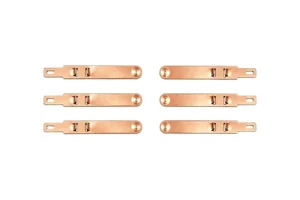
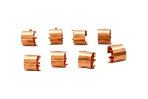
Most contact failures are decided long before production—they are designed in. A precision contact or terminal that looks correct on a CAD screen can be impossible to stamp, impossible to plate selectively, or impossible to hold to tolerance at volume. Design for Manufacturing (DFM) is the discipline of closing that gap early. This guide gives OEM hardware and electrical engineers a practical DFM checklist for custom precision contacts and terminals, drawn from HERSHEY’s 25 years of stamping, plating, and assembly experience. Browse the full range of custom precision contacts and terminals HERSHEY manufactures as you read.
Table of Contents
- What DFM Means for Precision Contacts
- Start With the Electrical Specification
- Geometry and Pitch: The Foundation
- Specify Material at the Design Stage
- Plating Strategy: Selective vs Full Immersion
- Tolerances and Dimensional Control
- The Prototype and Validation Path
- Common DFM Mistakes to Avoid
- Why Partner With HERSHEY for DFM
- Frequently Asked Questions
- Request a DFM Review
What DFM Means for Precision Contacts
For a precision contact, DFM is not a final review step—it is a continuous conversation between the electrical requirement and the manufacturing process. A good DFM outcome means the part is stampable on progressive or reel-to-reel dies, platable only where the interface sits, and inspectable without 100% manual measurement. Our complete guide to precision contacts and terminals covers what these parts are and where they are used; this article focuses on how to design them correctly the first time.
Quotable principle: The cheapest place to fix a contact design is on the drawing. Every tolerance, draft angle, and plating boundary you add to a CAD file either enables low-cost volume production or quietly pushes cost and risk into every single part you ship.
Start With the Electrical Specification
Before geometry, lock down the electrical truth. Share these numbers with your manufacturer up front:
- Rated current and duty cycle – continuous vs pulse current drives cross-section and plating thickness.
- Target contact resistance – for high-performance programs this is often below 10 mΩ; that single number dictates material and plating.
- Operating voltage and clearance – especially for EV and grid terminals where creepage distances matter.
- Mechanical life – insertion cycles or flex cycles set the spring-material and fatigue requirement.
- Signal vs power – signal contacts demand tighter geometry and cleaner plating than bulk power terminals.
A custom terminal built to a clear electrical spec avoids the most common failure mode: a part that is dimensionally perfect but electrically wrong.
Geometry and Pitch: The Foundation
Geometry is where stamping limits meet functional need. Three rules keep designs manufacturable:
- Respect minimum pitch. Pitch (center-to-center spacing) must be wide enough for the die to form and the plating to land selectively. Ultra-fine pitch is possible but drives tooling cost and scrap rate.
- Control spring arm length and deflection. Longer arms store more force but increase variation. Define the contact force window, not just a single number.
- Design for retention, not just contact. The clip or lance that holds the terminal in its housing is a separate function from the contact point—treat it as its own feature.

The same design logic applies whether you are making a battery cell-tab terminal or a fine-pitch micro-pin. Our precision contacts guide shows how one platform serves AI servers, EVs, and medical devices through geometry variation alone.
Specify Material at the Design Stage
Material choice is a spring-vs-conductivity trade-off made at the drawing stage, not after prototyping. The three production workhorses are beryllium copper (high strength and fatigue life), phosphor bronze (good conductivity at lower cost), and stainless steel (corrosion resistance and biocompatibility for medical). Specifying the alloy early lets the manufacturer recommend the right temper and strip thickness instead of guessing during sampling.
HERSHEY verifies every incoming coil by spectrometer analysis before stamping, so the material on your drawing is the material in your box—not an approximation.
Plating Strategy: Selective vs Full Immersion
Plating is usually the largest cost lever in a contact program. Selective plating deposits gold, silver, tin, or nickel only on the active interface; full immersion plates the entire strip. The DFM decision is simple: if only the contact point conducts, plate only the contact point.
Our complete guide notes that selective gold on a beryllium copper contact can keep resistance below 10 mΩ while using a fraction of the precious metal of full immersion. Design the plating window as a defined zone on the drawing—width, location, and minimum thickness—so it is repeatable on the reel-to-reel line.
Tolerances and Dimensional Control
Tolerance is the most abused field in contact drawings. Two principles keep it sane:
- Tolerate the function, not the feature. Tighten the dimension that affects contact force or fit; relax everything else. Over-tolerancing non-critical features multiplies inspection cost with zero reliability benefit.
- Know the equipment envelope. On German and Japanese high-speed presses, HERSHEY holds geometry to ±0.01 mm and plating to micro-inch control on stock as thin as 0.05 mm. Design within that envelope to avoid “special” processes.
A terminal designed with functional tolerances passes CCD dimensional inspection at line speed instead of being pulled for manual gauging.
The Prototype and Validation Path
A DFM review should always end in a physical sample, not a signed drawing. A typical HERSHEY path:
- DFM feedback (days 0–3): engineering reviews geometry, material, and plating window; recommends adjustments.
- Prototype (days 4–10): soft-tool or laser-cut samples are produced and measured.
- Validation: CCD dimensional check, salt-spray corrosion test, and life-cycle fatigue test confirm the design before hard tooling.
- Mass production (2–3 weeks): progressive dies ramp to volume with in-process force and torque monitoring.
Our precision contacts guide explains how the same production line serves both medical micro-pins and industrial blades once the prototype is locked.
Common DFM Mistakes to Avoid
- Uniform tight tolerances. Treating every dimension as critical destroys yield and cost.
- Pitch below strip capability. Designing pitch the die cannot form reliably guarantees scrap.
- Plating the whole part. Full immersion where only a point conducts wastes precious metal.
- Ignoring spring-back. Every alloy relaxes after forming; the drawing must account for it or the contact force drifts.
- Specifying material late. Choosing alloy after the shape is fixed limits the manufacturer’s ability to optimize.
Each of these is fixable at the drawing stage and expensive after tooling. Discuss them during a DFM review with the manufacturer rather than discovering them in a failed lot.
Why Partner With HERSHEY for DFM
HERSHEY’s integrated stamping and welding workshops—added in 2018—mean DFM feedback comes from the team that will actually make the part, not a separate trading company. With 100+ advanced production machines and IATF 16949 / ISO 9001 / ISO 13485 systems, the recommendations you receive are grounded in the capabilities of the line, not generic advice. Prototypes in 7–10 days let you validate the design before committing to hard tooling.
Frequently Asked Questions
When should I involve HERSHEY in the design phase?
As early as possible—ideally at the electrical specification stage. A DFM review before tooling avoids the most expensive corrections and typically shortens the path to a validated sample.
What pitch is too tight for stamping?
It depends on strip thickness and equipment, but pitch at or below the material thickness generally requires special tooling and raises scrap. Share your target pitch early so it can be validated against the press envelope.
How do you control plating thickness on selective areas?
Reel-to-reel selective plating deposits precious metal only on the defined contact window, with micro-inch thickness control verified during in-process inspection.
Can you prototype before finalizing tooling?
Yes. Soft-tool or laser-cut prototypes are typically delivered in 7–10 days, letting you validate geometry and plating before investing in progressive dies.
Do you sign an NDA for custom designs?
Yes. Custom contact and terminal designs are handled under standard NDA, and drawings are treated as customer-confidential throughout the program.
Request a DFM Review for Your Custom Contacts
Send your engineering drawings and electrical specification to HERSHEY for a practical DFM review—material recommendation, geometry and pitch check, plating-window definition, and a rapid prototype path. Start your DFM review or request a quote and turn a drawing into a validated, manufacturable contact.