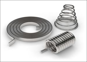
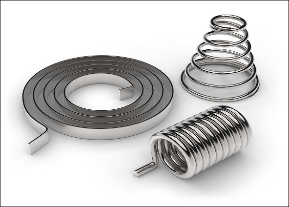
A constant force spring uses a pre-stressed flat metal strip to produce nearly constant pulling force over an extended travel distance. As the strip unwinds from its natural coil, it tries to return to its original curvature, creating the force that drives the mechanism. The force typically approaches a stable operating range after approximately 1.25 times the natural coil diameter (D) of extension. At maximum extension, at least 1.5 wraps should remain on the drum as a preliminary design guideline. This guide covers how constant force springs work, how to size and select them, how to install them correctly, and how to prevent common failures in engineering applications.
Quick Decision Card — Is a Constant Force Spring the Right Choice?
Use It When
Choose a constant force spring when a mechanism needs a nearly stable pulling force over a long stroke and has limited space for a conventional spring.
- Long travel: The spring can provide extended linear movement without requiring a long spring body.
- Stable pulling force: The mechanism needs approximately the same force throughout most of its working stroke.
- Compact storage: The strip winds into a coil, making it suitable for assemblies with limited installation space.
- Automatic retraction: The spring pulls cables, hoses, covers, or moving components back toward their original positions.
- Counterbalancing: It offsets part of the weight of sliding panels, access covers, and other moving components.
Avoid It When
A constant force spring is not suitable when the mechanism requires a different force profile or cannot maintain the strip’s intended bending direction.
- Increasing force is required: An extension or compression spring may be more suitable when resistance needs to increase with travel.
- High initial force is essential: The initial unwinding region may not provide the required pulling force.
- Reverse bending cannot be avoided: Repeated back-bending can damage the strip and shorten fatigue life.
- A positive stopping function is needed: The spring produces force but does not lock or stop a moving component.
What You Need Before Selecting
Define these requirements before requesting a quotation. They determine whether a constant force spring can meet the application’s load, travel, and service-life requirements.
- Required pulling force and allowable force variation.
- Working travel and total strip length.
- Expected operating cycles and service life.
- Available space for the coil, drum, and extension path.
- Mounting arrangement and pulling direction.
- Operating speed and installation orientation.
- Material, corrosion resistance, temperature, and compliance requirements.
What a Constant Force Spring Is and How It Produces a Flat Force Curve
A constant force spring is a pre-stressed flat metal strip wound into a compact coil. Pulling the free end causes the strip to unwind and bend toward a flatter shape. Its tendency to recover its original curvature produces a pulling force.
Unlike a conventional helical spring, which generally changes force as it extends or compresses, a constant force spring can maintain relatively stable force over most of its working travel. This behavior comes from the strip’s pre-stressed geometry, not simply from the material used.
Construction: Pre-Stressed Flat Strip and Constant-Radius Coil
The spring consists of a thin, flat metal strip formed with an initial curvature and wound into a coil. This pre-stressed condition allows the strip to generate force when it unwinds.
A typical assembly includes:
- Spring strip: The flat metal element that stores elastic energy and produces the pulling force.
- Natural coil: The coil formed by the strip’s pre-stressed curvature.
- Inner end: The end secured to a drum, shaft, or designated mounting feature.
- Outer end: The free end connected to the moving component.
- Drum or support: The mounting structure that supports the coil and maintains the intended winding arrangement.
When the outer end is pulled, the strip leaves the coil and gradually straightens. Its elastic recovery creates the force needed to retract the moving component.
The natural coil diameter is an important design dimension. It affects the strip’s initial curvature, the force transition, and the relationship between the spring and its mounting drum.
Force-Displacement Curve: Initial Ramp and the 1.25×D Plateau
A constant force spring does not necessarily deliver its rated force from the first millimeter of extension. Its force-displacement curve typically has an initial transition followed by a relatively flat operating region.
Let D represent the natural coil diameter. A commonly used preliminary guideline is that the spring approaches its plateau after approximately 1.25D of extension. This value is a design reference, not a universal transition point.
The operating curve can be divided into three regions:
- Initial extension: The strip begins to unwind. Its force changes as the strip transitions away from its natural coil.
- Transition region: The strip moves toward its normal working bending condition.
- Plateau region: The pulling force becomes relatively stable over the useful working travel.
For example, a spring with a 30 mm natural coil diameter has a preliminary transition reference of:
1.25 × 30 mm = 37.5 mm
This does not mean every spring reaches its rated force at exactly 37.5 mm. The actual transition depends on the pre-stress, strip dimensions, material, and winding geometry. Confirm it using the manufacturer’s force-displacement data.
When selecting a spring, check three separate values:
- Initial pulling force.
- Rated force in the plateau region.
- Force variation across the complete working stroke.
Why Geometry, Not a Special Material, Creates the Constant Force
The nearly constant force comes from the relationship between the strip’s natural curvature and its changing shape during unwinding.
As the strip leaves the coil, it bends toward a flatter condition. The strip’s elastic recovery creates a restoring moment. Under suitable operating conditions, this produces a relatively stable pulling force over much of the extension range.
Material properties still matter. Elastic modulus, yield strength, fatigue resistance, and surface condition affect how the strip responds to repeated bending. However, choosing a high-strength alloy alone does not create a constant force curve.
The final performance depends on several factors working together:
- Pre-stressed curvature established during manufacturing.
- Strip width and thickness.
- Natural coil diameter.
- Material elastic modulus.
- Manufacturing consistency and surface quality.
Key Variables: Width, Thickness, Coil Diameter, and Material Modulus
Four variables have a direct influence on constant force spring design.
| Variable | Primary Influence | Design Consideration |
|---|---|---|
| Strip width (b) | Load capacity and cross-sectional area. | Increasing width generally increases force capacity when other conditions remain comparable. |
| Strip thickness (t) | Bending stiffness and stress. | Thickness has a strong effect on bending behavior and must be checked against fatigue requirements. |
| Natural coil diameter (D) | Initial curvature and winding geometry. | Affects the transition region and compatibility with the mounting arrangement. |
| Elastic modulus (E) | Elastic response of the material. | Influences the relationship between bending deformation and restoring force. |
These variables should not be adjusted independently. For example, increasing strip width may increase force capacity, while increasing thickness can significantly change both bending stiffness and stress.
The final dimensions should be established through engineering calculations and verified against the manufacturer’s performance data.
Constant Force vs. Other Spring Types — A Selection Matrix
Constant force springs, extension springs, constant torque springs, power springs, and gas springs can all support moving components. The difference is how they produce force or torque throughout their operating range.
Use the required motion and force profile to choose between them.
Constant Force Spring vs. Standard Extension Spring
A constant force spring provides relatively stable pulling force over most of its working stroke. A standard extension spring generally produces increasing force as it stretches.
| Design Factor | Constant Force Spring | Extension Spring |
|---|---|---|
| Force-displacement curve | Relatively flat after the initial transition. | Generally increases with extension. |
| Typical travel | Suitable for relatively long linear travel. | Limited by spring length, allowable extension, and stress. |
| Space requirement | Compact coiled storage. | Requires axial space for the spring body and extension. |
| Initial force | Depends on the initial unwinding region. | May include initial tension. |
| Suitable applications | Retraction and long-travel counterbalancing. | Mechanisms requiring increasing pulling force. |
Choose a constant force spring when the load should remain relatively stable as a component moves. Choose an extension spring when the mechanism needs progressively greater resistance.
Constant Force Spring vs. Constant Torque Spring
Both designs use pre-stressed flat strips, but they deliver different types of output. A constant force spring produces linear pulling force, while a constant torque spring produces rotational torque.
| Design Factor | Constant Force Spring | Constant Torque Spring |
|---|---|---|
| Output | Approximately constant linear force. | Approximately constant rotational torque. |
| Typical travel | Linear extension and retraction. | Rotational movement over multiple turns. |
| Space requirement | Coil with a linear pulling path. | Coil with a rotational mounting arrangement. |
| Initial output | May include an initial force transition. | Depends on preload and rotational geometry. |
| Suitable applications | Linear counterbalancing and retraction. | Rotary return and rotational mechanisms. |
The deciding factor is the required movement. If the mechanism needs a straight-line pulling force, consider a constant force spring. If it needs rotational return torque, consider a constant torque spring.
Constant Force Spring vs. Power Spring
A power spring, also called a clock spring in many applications, stores energy as it is wound and releases it as rotational torque. A constant force spring is designed to provide linear pulling force as its strip unwinds.
| Design Factor | Constant Force Spring | Power Spring |
|---|---|---|
| Output | Relatively constant linear force. | Rotational torque that depends on design and operating condition. |
| Typical travel | Linear extension. | Rotational winding and unwinding. |
| Space requirement | Coil and linear extension path. | Rotational housing or spring compartment. |
| Initial output | May include an initial force transition. | Depends on preload and spring geometry. |
| Suitable applications | Linear retraction and counterbalancing. | Rotational energy storage and return mechanisms. |
Do not select a power spring simply because it also uses flat spring strip. Match the spring type to the required output: linear force or rotational torque.
Constant Force Spring vs. Gas Spring and Other Counterbalance Options
Gas springs, counterweights, and constant force springs can all assist moving panels and covers. Their force characteristics and installation requirements differ.
| Design Factor | Constant Force Spring | Gas Spring | Counterweight |
|---|---|---|---|
| Force-displacement curve | Relatively flat working force. | Depends on gas pressure, rod area, friction, and temperature. | Approximately constant gravitational force. |
| Typical travel | Long linear extension. | Limited by cylinder stroke. | Depends on available space and pulley arrangement. |
| Space requirement | Compact coil and strip path. | Requires cylinder length and mounting clearance. | Requires space for the moving weight. |
| Initial output | May have an initial force transition. | May have substantial initial extension force. | Determined by mass and mechanism geometry. |
| Suitable applications | Compact linear counterbalancing. | Controlled lifting and support. | Heavy loads with sufficient installation space. |
A constant force spring is useful when a mechanism needs a compact retraction or counterbalancing solution. A gas spring may be more suitable when damping or controlled lifting assistance is required. A counterweight is worth considering when the assembly has enough room for a moving mass and pulley system.
When Not to Use a Constant Force Spring — Boundaries and Alternatives
A constant force spring should match the required force profile, travel, and installation geometry. If the mechanism requires a different type of movement or loading behavior, another solution may perform better.
When Force Must Ramp with Travel
A constant force spring is designed to maintain relatively stable pulling force after its initial transition. It is not the best choice when resistance must increase as the mechanism moves.
For example, a sliding mechanism may need low resistance near its starting position and greater resistance toward the end of its travel. A conventional extension spring can provide this progressive force behavior more directly.
Alternative: Consider an extension spring, compression spring, or custom variable-force mechanism. Select the design according to the required force-displacement curve.
When You Need High Initial Force or a Stopping Function
The initial unwinding region may not provide the same force as the established operating plateau. If a mechanism needs a high pulling force immediately after movement begins, a constant force spring may not meet the requirement.
It also cannot replace a mechanical stop. The spring continues applying force when a moving component reaches its travel limit. Without a separate stop, the strip, attachment, or surrounding structure may be overloaded.
Alternative: Consider a spring with a suitable initial force characteristic, a gas spring, or a dedicated mechanical stop. Use a separate locking mechanism when the application requires positive load retention.
When Back-Bending or Reverse Bending Is Unavoidable
Constant force springs are designed to unwind in a specific direction. During normal operation, the strip moves from its natural coil toward a flatter shape.
Forcing it around a guide or roller in the opposite direction adds bending stress. Repeated reverse bending can cause permanent deformation, surface damage, and fatigue cracking.
Alternative: Redesign the strip path to maintain its intended bending direction. If reverse bending cannot be eliminated, consider another spring arrangement or request a specific engineering assessment from the manufacturer.
When Space, Life, or Material Constraints Dominate
A compact spring does not guarantee a compact assembly. The design still needs room for the natural coil, mounting drum, attachment points, guides, and extension path.
Fatigue life can also become a limitation. Excessive bending stress, damaged strip edges, corrosion, or unsuitable material can cause early failure even when the rated force is correct.
Alternative: Review the strip dimensions, material, coil geometry, and installation arrangement. If the required service life cannot be achieved within the available space, consider another spring technology rather than forcing an unsuitable design.
Selection Workflow — From Duty Cycle to Spring Geometry
Start with the application’s load and movement requirements. Then determine the spring geometry, check fatigue performance, select the mounting arrangement, and validate the design with actual samples.
Step 1 — Define Force, Travel, and Allowable Force Variation
First, determine how much force the mechanism needs throughout its complete working stroke.
- Rated force: The pulling force required to move or balance the component.
- Working travel: The distance between the fully retracted and fully extended positions.
- Allowable variation: The permitted difference between the minimum and maximum operating force.
- Initial force: The force available during the first part of unwinding.
- Operating speed: How quickly the spring extends and retracts.
- Duty cycle: The expected number of operating cycles per day and over the intended service life.
For counterbalancing applications, also calculate the moving component’s weight and the mechanical advantage of the linkage.
Do not assume the spring force must equal the component’s weight. A pulley or lever changes the force required at the spring attachment. Calculate the actual load using the mechanism’s geometry.
Step 2 — Calculate Required Strip Thickness, Width, and Coil Diameter
After defining the load and travel, determine the strip dimensions and winding geometry.
The main design variables are:
- Strip thickness (t): Affects bending stiffness, restoring force, and bending stress.
- Strip width (b): Affects load capacity and the overall width of the assembly.
- Natural coil diameter (D): Determines the initial curvature and influences the transition region.
- Strip length (L): Must cover the required travel while retaining enough material on the drum.
For a rectangular strip bending through its thickness, the second moment of area is:
I = bt3 / 12
The corresponding bending stiffness is:
EI = Ebt3 / 12
Where:
- E = Elastic modulus of the material.
- b = Strip width.
- t = Strip thickness.
- I = Second moment of area.
These equations describe the strip’s bending stiffness. They are not complete formulas for the output force of a constant force spring. The actual force also depends on pre-stressed curvature, winding geometry, and boundary conditions.
For preliminary layout, use approximately 1.25D as a reference for the initial transition distance. Confirm the actual transition point using the manufacturer’s force-displacement curve.
Do not finalize strip dimensions from a simplified equation alone. The manufacturer should verify force, stress, coil geometry, and available travel for the selected material and manufacturing process.
Step 3 — Check Stress, Fatigue Life, and Material
A spring can meet its force requirement and still fail early if the strip experiences excessive bending stress or repeated damage at its edges.
Review these factors before selecting the material:
- Working stress: Check the bending stress under the intended operating curvature.
- Fatigue performance: Evaluate the expected number of extension and retraction cycles.
- Surface condition: Scratches, edge defects, and corrosion pits can initiate fatigue cracks.
- Temperature: Confirm that the material and surface treatment suit the operating temperature.
- Corrosion resistance: Consider humidity, chemicals, and exposure conditions.
High-carbon spring steel can provide suitable mechanical performance in controlled environments. Stainless spring steel may be more appropriate where corrosion resistance is important.
However, material selection must account for more than corrosion resistance. Grade, thickness, forming process, heat treatment, and surface quality all affect performance. Evaluate them together.
Step 4 — Choose Drum-Mounted vs. Clip-On Configuration
The mounting arrangement determines how the inner end is secured and how the strip travels during operation.
Drum-mounted: The inner coil is supported by a drum or shaft. This arrangement provides a defined mounting position and controlled winding geometry.
Clip-on: A dedicated clip or attachment feature secures the spring. It can simplify installation in suitable assemblies, provided the clip supports the spring without damaging or distorting the strip.
Self-coiling: The strip stores in its natural coil and extends when the free end is pulled. The surrounding housing must provide sufficient clearance and guidance.
Compare the available space, attachment method, drum dimensions, maintenance access, and required travel before choosing a configuration.
Step 5 — Validate with Supplier Data, CAD, and Samples
Do not approve a spring based only on nominal dimensions or theoretical calculations. Check the actual performance data and test a sample in the intended mechanism.
Request the following information:
- Force-displacement data across the working stroke.
- Natural coil diameter and recommended drum dimensions.
- Minimum remaining wraps at maximum extension.
- Material grade, strip thickness, width, and surface finish.
- Recommended operating travel and extension direction.
- Cycle-life data and test conditions.
- CAD drawings and mounting dimensions.
During sample testing, measure initial pull, plateau force, retraction behavior, alignment, and performance after repeated cycling. Check for rubbing, twisting, and interference under actual installation conditions.
Worked Example — Sizing Length and Load for a Long-Travel Retraction Application
Consider a retractable cable-management assembly that needs to pull a cable carrier back into its housing. The mechanism requires 500 mm of useful travel and a relatively stable pulling force of 20 N.
The following example estimates the strip length needed for preliminary layout. It does not establish a production-ready spring specification.
Inputs and Assumptions
| Parameter | Assumed Value |
|---|---|
| Required working force | 20 N |
| Useful plateau travel | 500 mm |
| Natural coil diameter (D) | 30 mm |
| Strip thickness (t) | 0.20 mm |
| Strip width (b) | 15 mm |
| Minimum remaining wraps | 1.5 turns |
For this example, the 500 mm requirement represents useful travel within the relatively stable force region. The initial transition distance is added separately.
Calculation
1. Estimate the initial transition distance.
Use the preliminary 1.25D guideline:
Transition distance = 1.25 × D
= 1.25 × 30 mm = 37.5 mm
The preliminary design therefore allows approximately 37.5 mm for the initial transition before the useful plateau travel begins.
2. Calculate the active strip length.
Active strip length = Transition distance + Useful plateau travel
= 37.5 mm + 500 mm = 537.5 mm
The spring needs approximately 537.5 mm of active strip outside the retained winding to cover the assumed movement.
3. Estimate the retained length for 1.5 wraps.
For a simplified estimate, assume the retained wraps follow a constant 30 mm reference diameter:
Retained length = 1.5 × π × D
= 1.5 × 3.1416 × 30 mm
≈ 141.4 mm
This is a simplified estimate. The actual retained length depends on the winding diameter and drum geometry. The manufacturer should calculate it using the actual assembly dimensions.
4. Estimate the preliminary total strip length.
Total strip length = Active strip length + Retained length
= 537.5 mm + 141.4 mm
≈ 678.9 mm
The preliminary strip length is approximately 679 mm, before adding any material required for inner-end and outer-end attachments or manufacturing allowances.
5. Verify the required force.
The target force is 20 N, but the assumed 15 mm width and 0.20 mm thickness do not automatically guarantee this output.
The manufacturer must verify the force using the actual material grade, pre-stressed curvature, coil diameter, and manufacturing process. The design must also satisfy the required stress and fatigue limits.
Interpretation and Common Errors
The calculation provides a preliminary length estimate. It does not confirm that the spring will deliver 20 N or achieve the required cycle life.
Check these points before releasing the design:
- Do not omit the transition region: The useful plateau travel may require additional extension before it begins.
- Retain sufficient wraps: At least 1.5 wraps should remain at maximum extension under the stated design guideline.
- Use the actual winding geometry: A constant reference diameter is only a simplified estimate.
- Verify the force independently: Width and thickness alone cannot establish the rated load.
- Allow for attachments: Inner-end and outer-end mounting features may require additional strip length.
Before production, confirm the force curve, maximum extension, remaining wraps, and fatigue performance using manufacturer data and physical samples.
Mounting Configurations and Installation Rules
Correct mounting prevents twisting, excessive bending, and premature wear. The spring must follow its intended unwinding direction, remain properly supported, and have enough clearance throughout the full stroke.
Drum-Mounted vs. Clip-On / Self-Coiling Configurations
Drum-mounted springs use a drum or shaft to support the inner coil. This arrangement provides a defined attachment point and controlled winding geometry.
Clip-on configurations use a dedicated clip or attachment feature. They can simplify installation when the surrounding structure provides suitable support.
Self-coiling springs store the strip in their natural coil without relying on a conventional drum arrangement. They still need adequate housing clearance and guidance.
| Configuration | Main Advantage | Installation Consideration |
|---|---|---|
| Drum-mounted | Defined inner-end support and winding geometry. | Drum diameter, attachment, and winding direction must match the spring design. |
| Clip-on | Can simplify attachment in suitable assemblies. | The clip must retain the spring without slipping or damaging the strip. |
| Self-coiling | Compact storage without a conventional drum arrangement. | The coil needs clearance, support, and guidance. |
Minimum 1.5 Wraps at Maximum Extension
At least 1.5 wraps should remain on the drum at maximum extension as a preliminary design guideline. The retained strip supports the winding and helps prevent the spring from being pulled completely off its mounting arrangement.
Calculate the remaining wraps at the fully extended position, not when the spring is at rest. This is the condition in which the least strip remains on the drum.
Verify the following:
- Maximum operating travel.
- Actual winding and drum diameter.
- Strip length remaining at full extension.
- Inner-end attachment method.
- Manufacturer’s minimum wrap requirement.
The 1.5-wrap value is a practical reference. Follow the manufacturer’s specified minimum if it is greater.
Drum Diameter vs. Natural Coil Diameter
These two dimensions describe different parts of the spring assembly.
Natural coil diameter: The diameter of the spring in its free, naturally coiled condition.
Drum diameter: The diameter of the mounting component around which the spring is supported or wound.
A drum that is too small can force the strip into excessive curvature and increase bending stress. An unsuitable oversized drum can also change the winding geometry and affect spring performance.
Do not assume the drum diameter should always equal the natural coil diameter. Use the manufacturer’s recommended dimensions for the specific spring design.
Guiding and Anti-Twist Measures
The strip should extend along a controlled path. Pulling it at an angle can cause twisting, uneven edge loading, or contact with the housing.
During installation:
- Align the spring and moving attachment points.
- Prevent lateral movement that causes the strip to rub against the housing.
- Provide clearance for the coil to expand and contract.
- Remove sharp edges near the strip’s travel path.
- Make sure the attachment does not twist the strip during operation.
Guides should control the strip without creating excessive friction. Unnecessary contact can damage the surface and interfere with smooth extension and retraction.
Idler and Back-Bending Limits
Idlers can redirect or support the strip, but their diameter and position must suit the spring’s intended bending direction.
A guide roller should not force the strip to bend in the opposite direction of its normal unwinding movement. Repeated reverse bending adds stress and can shorten fatigue life.
Before adding an idler, check:
- Roller diameter.
- Roller position and contact angle.
- Strip alignment.
- Clearance throughout the complete travel.
- Whether the roller introduces reverse bending.
If the strip passes around several rollers, evaluate the entire path. Do not assess each roller in isolation.
Common Failure Modes and Misuse Corrections
Constant force spring failures often start with incorrect mounting, excessive bending, insufficient retained wraps, or unsuitable material selection. The following problems should be checked during design and troubleshooting.
Back-Bending the Strip
Issue: A guide, idler, or attachment forces the strip to bend opposite to its normal unwinding direction. Repeated reverse bending can cause permanent deformation, surface damage, and fatigue cracks.
Expert Recommendation: Keep the strip moving in its intended bending direction. Review the complete guide and roller arrangement. If reverse bending cannot be eliminated, obtain manufacturer approval for the specific operating condition or consider another spring arrangement.
Using the Spring as a Stopping Mechanism
Issue: The moving component reaches the end of its travel while the spring continues pulling. The resulting load can damage the strip, attachment, or surrounding structure.
Expert Recommendation: Install a separate mechanical stop or travel-limiting feature. The stop must prevent overextension and handle the loads generated when the moving component reaches its limit.
Too Few Wraps on the Drum
Issue: Excessive extension leaves too little strip material on the drum. The inner coil may lose support or become detached from its intended mounting arrangement.
Expert Recommendation: Calculate the remaining wraps at maximum extension. Maintain at least 1.5 wraps as a preliminary guideline, or follow the manufacturer’s higher requirement. Add a mechanical travel limit to prevent overextension.
Attaching the Inner End to a Spool Incorrectly
Issue: An unsuitable hole, clamp, fastener, or spool feature can cause the inner end to slip or create concentrated stress. Incorrect attachment can also interfere with the intended winding direction.
Expert Recommendation: Follow the manufacturer’s attachment design. Check fastener clearance, retention, and loading direction. Do not drill, cut, or modify the strip without approval because these changes can create stress concentrations and weaken the material.
Drum Too Small or Too Large for the Natural Coil
Issue: An unsuitable drum changes the strip’s bending condition. A drum that is too small may increase bending stress, while an oversized or incorrectly positioned drum may interfere with the intended winding geometry.
Expert Recommendation: Confirm the recommended drum diameter using the manufacturer’s design data. Evaluate the natural coil diameter and mounting geometry together rather than selecting the drum based only on the available shaft or housing dimensions.
Material and Cycle-Life Mismatch
Issue: The material or strip thickness cannot withstand the required operating cycles or environmental conditions. The spring may develop edge cracks, corrosion, permanent deformation, or a change in force.
Expert Recommendation: Specify the cycle count, temperature, humidity, chemical exposure, and operating speed before selecting the material. Request fatigue-test data under representative conditions. Check strip edges and surface quality before approving production samples.
Applications by Motion Requirement, Not by Industry
Constant force springs are most useful when an application needs a specific movement pattern: long-travel counterbalancing, stable pulling tension, or automatic retraction. The same operating principle can support equipment in several industries.
Long-Travel Counterbalance
A constant force spring can offset part of the weight of a moving component over an extended travel distance.
Typical applications include:
- Sliding panels.
- Retractable covers.
- Equipment access doors.
- Vertically moving assemblies.
For vertical applications, calculate the moving load and linkage ratio. Provide independent safety support where required. The spring should not be the only component holding a suspended load.
Constant-Tension Retraction
Retractable cables, straps, and moving assemblies often need a pulling force that remains relatively stable as they extend.
A constant force spring can pull the moving element back when the external force is removed. Its rated force must be high enough to overcome friction and resistance in the mechanism, but not so high that it creates excessive tension.
Check the complete retraction path, attachment strength, and required return speed before selecting the spring.
Space-Constrained Cable and Hose Management
Equipment with moving cables or hoses often needs a compact mechanism to control slack and return the assembly after extension.
Constant force springs can store their strip in a small coil while providing pulling force over a longer distance. Potential applications include retractable cable assemblies, hose-management systems, and movable equipment connections.
Match the spring force to the cable or hose weight and resistance. Keep the strip away from sharp edges, contaminants, and excessive lateral movement.
Constant-Load Mechanisms in Medical and Small Devices
Compact medical and electronic devices may need a moving component to return under a relatively stable load. A constant force spring can support retractable assemblies, adjustable supports, moving covers, and compact positioning mechanisms.
Material selection requires additional attention in regulated equipment. Check material traceability, corrosion resistance, cleanliness, and applicable regulatory requirements. Mechanical performance alone does not establish compliance for the finished device.
Door Closers, Gym Equipment, and Industrial Retraction
Selected door mechanisms, exercise equipment, and industrial assemblies can also use constant force springs.
- Door mechanisms: Assist the movement or counterbalance of suitable sliding panels and covers.
- Gym equipment: Provide pulling force in selected adjustable or retractable mechanisms.
- Industrial equipment: Retract cables, maintain tension, and support moving components.
Not every door, exercise machine, or lifting system is suitable. Check the required force curve, travel, mounting conditions, and safety requirements before choosing this spring type.
Specifying and Sourcing — RFQ Checklist for Constant Force Springs
A useful request for quotation should include the spring’s operating requirements, installation dimensions, material conditions, and service-life target. Sending only a force value and approximate strip length is rarely enough for a reliable design.
Performance Data to Provide
Start with the load and movement requirements:
- Required rated pulling force.
- Minimum and maximum acceptable force.
- Maximum working travel.
- Initial force requirement.
- Operating speed and movement frequency.
- Expected cycles per day and total service life.
- Continuous or intermittent operating conditions.
If possible, provide a force-displacement diagram. It helps the manufacturer determine whether a constant force spring can meet the load requirements throughout the stroke.
Mechanical Envelope and Mounting Constraints
Provide the dimensions of the complete installation area, not just the spring itself.
- Maximum natural coil diameter.
- Available housing width and depth.
- Drum diameter and shaft dimensions, if applicable.
- Mounting holes, clips, and attachment requirements.
- Available strip extension path.
- Required minimum remaining wraps.
- Guide, idler, and roller positions.
- Installation orientation and pulling direction.
A CAD model or dimensioned assembly drawing helps the manufacturer identify interference, alignment, and mounting problems before producing samples.
Material, Plating, and Compliance
Specify the operating environment before choosing the spring material and surface treatment.
- Preferred spring material or acceptable alternatives.
- Required strip thickness and width, if already established.
- Surface finish or protective coating.
- Corrosion resistance requirements.
- Operating temperature range.
- Exposure to moisture, cleaning agents, or chemicals.
- Applicable material and regulatory requirements.
Surface treatments must withstand repeated bending. A coating that performs well on a static component may crack, peel, or wear when applied to a strip that continuously winds and unwinds.
Life Test and Acceptance Criteria
Define the expected cycle life before production. The test should represent the actual operating conditions, including travel, speed, load, installation geometry, and relevant environmental exposure.
Agree on measurable acceptance criteria, such as:
- Force variation within the specified operating range.
- No visible cracking or unacceptable permanent deformation.
- No unacceptable corrosion or surface damage.
- No slipping or detachment at mounting points.
- Acceptable retraction performance after the specified cycle test.
- Dimensional consistency within agreed tolerances.
Do not rely on a cycle-life figure without its test conditions. Fatigue performance depends on material, stress, geometry, surface quality, installation, and operating environment.
CAD, Samples, and Supplier Validation
Before approving production, request the information needed to check both the spring and its integration into the assembly.
- Dimensioned spring drawings.
- CAD files for the spring and mounting components.
- Material and dimensional specifications.
- Force-displacement test data.
- Sample quantity and lead time.
- Cycle-test results or an agreed validation plan.
- Production inspection and acceptance criteria.
Test samples in the actual equipment whenever possible. A spring that performs correctly on a test fixture may behave differently when installed with real guides, cable loads, friction, and mounting tolerances.
For a custom constant force spring, provide the required force, working travel, mounting dimensions, material conditions, and service-life target. Contact the engineering team to discuss your application, review the design requirements, and evaluate a suitable spring configuration.
FAQ
Constant Force Spring vs. Extension Spring — What Changes in Design?
A constant force spring uses a pre-stressed flat strip that unwinds from a coil and provides relatively stable pulling force over most of its working travel. A conventional extension spring uses a helical coil and generally increases its pulling force as it extends. Choose a constant force spring for long-travel applications with a relatively stable load. Choose an extension spring when resistance should increase with movement.
How Do I Determine the Length for a Constant Force Spring?
Calculate the useful working travel, initial transition distance, retained wraps, and attachment allowances. A preliminary transition estimate is approximately 1.25 times the natural coil diameter. At maximum extension, maintain at least 1.5 wraps on the drum as a practical design guideline. Use the actual winding geometry for the final calculation and confirm the result with the manufacturer.
Why Is the Force Not Constant at the Beginning of Travel?
The strip must transition from its natural coiled condition into its normal unwinding condition. During this movement, its bending geometry changes, so the pulling force may rise or vary before reaching the plateau. The exact transition depends on pre-stress, material, strip dimensions, and coil geometry.
Can a Constant Force Spring Be Back-Bent?
Normal operation should follow the intended unwinding direction. Reverse bending introduces additional stress and can cause permanent deformation, surface damage, or fatigue failure. Avoid back-bending unless the manufacturer has specifically evaluated and approved the design for that condition.
How Many Wraps Should Remain on the Drum?
A common preliminary design guideline is to retain at least 1.5 wraps at maximum extension. The actual requirement depends on the spring and mounting arrangement. Follow the manufacturer’s specified minimum if it is greater.
What Materials and Thicknesses Are Typical?
Constant force springs commonly use high-carbon spring steel or stainless spring steel. The appropriate material depends on force requirements, fatigue performance, corrosion resistance, temperature, and operating environment. Strip thickness varies with the application. There is no single standard thickness suitable for every design, so the manufacturer should confirm the grade and dimensions.
How Do I Estimate Cycle Life?
Cycle life depends on material, strip thickness, working stress, natural coil diameter, surface condition, installation geometry, and operating environment. Preliminary calculations help assess the design, but physical testing is necessary to validate service life. Define the required cycle count and operating conditions, then request representative fatigue-test data.
Glossary and Unit Conventions
Use these terms consistently when discussing constant force spring specifications and performance.
- Rated load: The specified pulling force under defined operating conditions, usually expressed in newtons (N) or pounds-force (lbf).
- Plateau: The relatively flat section of the force-displacement curve where the spring delivers approximately stable force.
- Natural coil diameter: The diameter of the spring in its free, naturally coiled condition.
- Drum diameter: The diameter of the mounting drum or support around which the spring is installed.
- Wrap: One complete turn of the spring strip around the drum or coil.
- Back-bending: Bending the strip opposite to its intended normal unwinding direction.
- Constant torque spring: A pre-stressed strip spring designed to deliver approximately stable rotational torque rather than linear pulling force.
- Working travel: The specified extension distance over which the spring operates.
- Initial transition: The early extension region in which the spring moves toward its relatively stable force range.
- Cycle life: The number of complete operating cycles a spring can withstand under defined test conditions before reaching a specified failure or performance limit.
Use consistent units throughout the design process. Strip dimensions, coil diameter, drum diameter, and travel are commonly specified in millimeters (mm). Force is usually expressed in newtons (N). When comparing supplier data, check that the measurement conditions and dimensional references are the same.